Configuring the LAN interface, including DHCP server
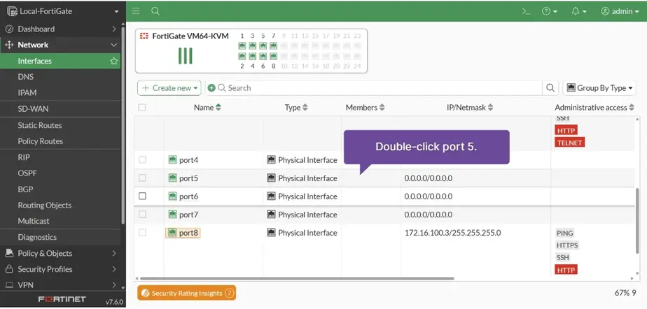
Network > Interfaces > doble-click on port5
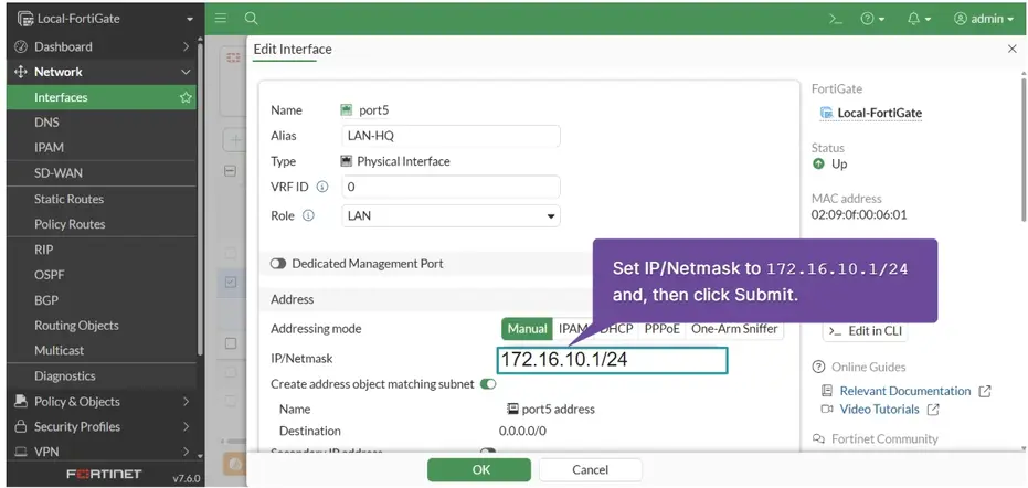
Alias: LAN-HQ Role: LAN IP/Netmask 172.16.10.1/24
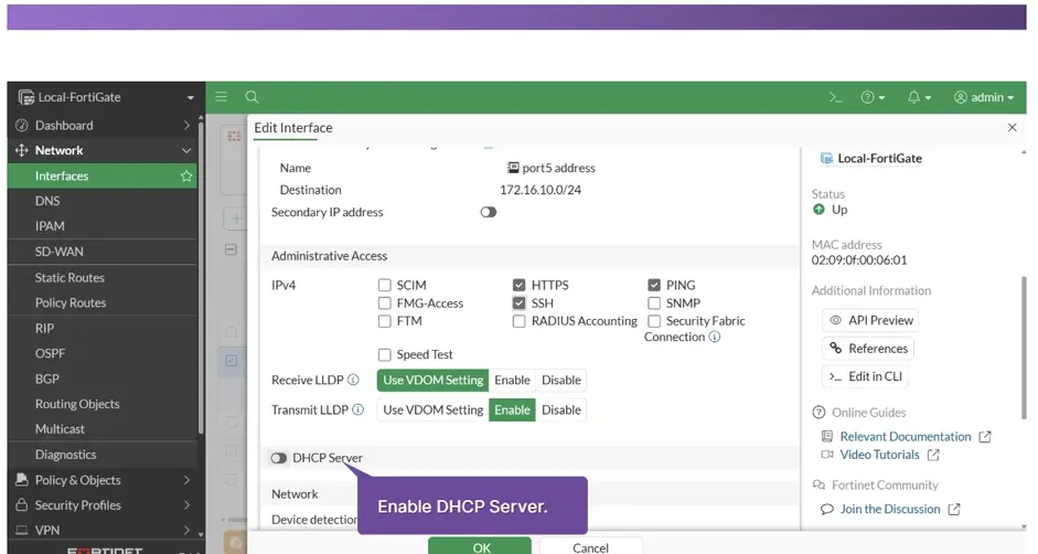
Administrative Access IPV4 : HTTPS, PING, SSH after Enable DHCP Server
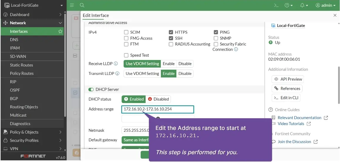
Address range: 172.16.10.21-172.16.10.256
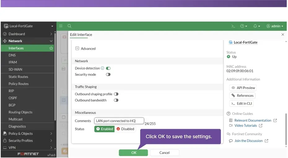
Comments: Lan port connected to HQ and click OK
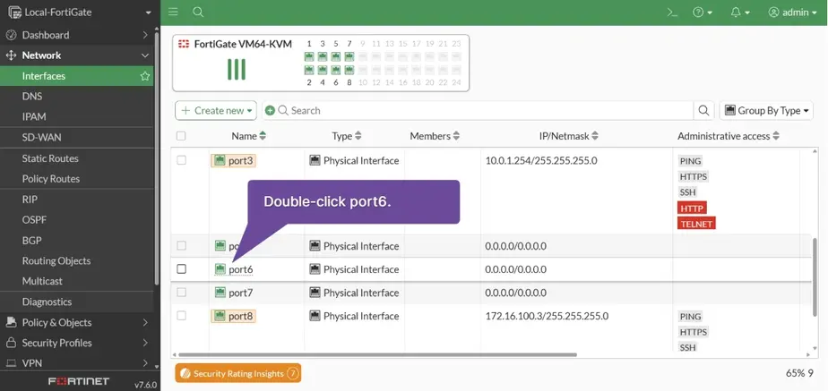
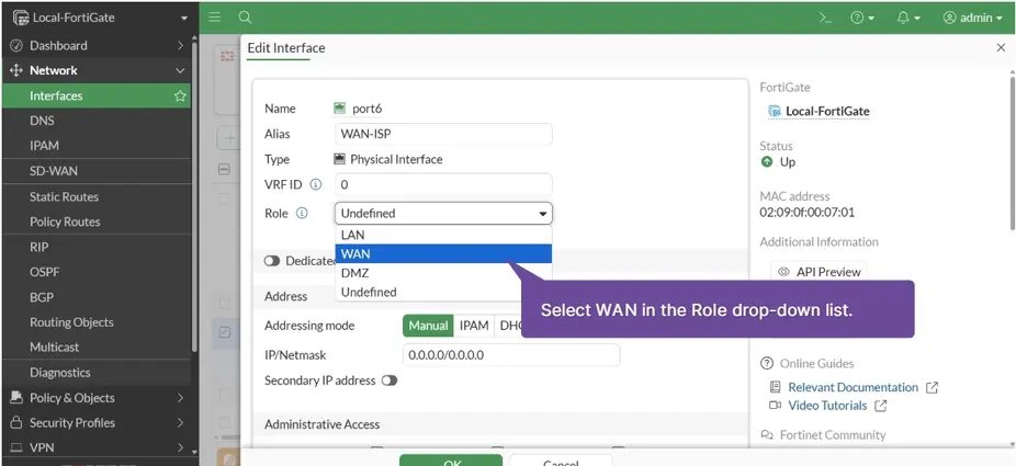
Double-click on port6
Alias: WAN-ISP Role: WAN
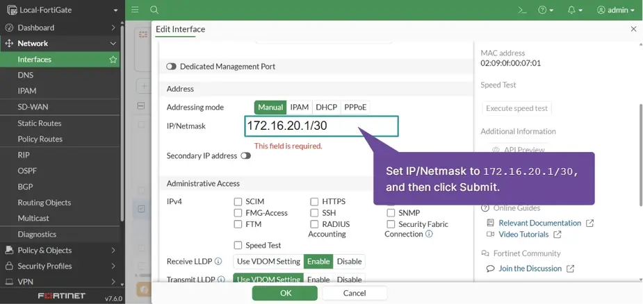
IP/Netmask: 172.16.20.1/30 and IPV4: SSH
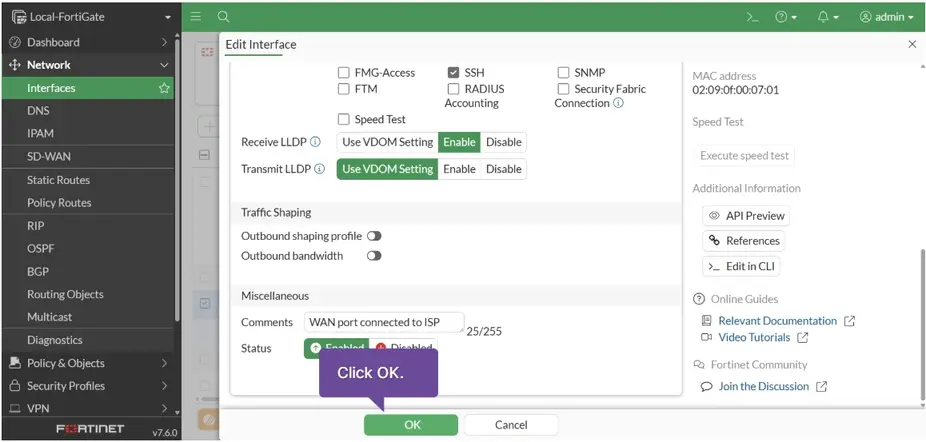
Comments: WAN port connected to ISP and click OK
Configuration of the LAN and WAN interfaces is complete.
Configure and monitor the default route
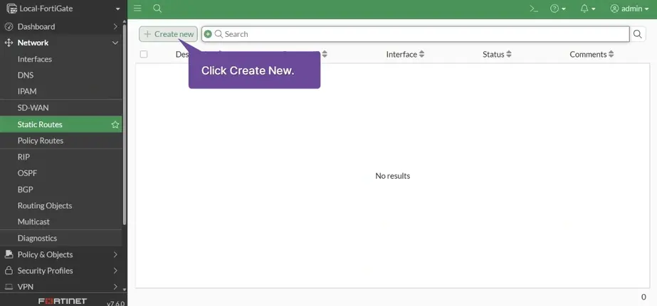
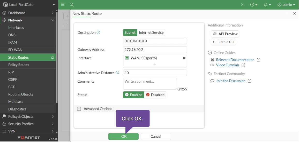
Network > Static Routes > click create New
Destination Subnet : 0.0.0.0/0 Gateway Address: 172.16.20.2 Interface: WAN-ISP (port6) and OK
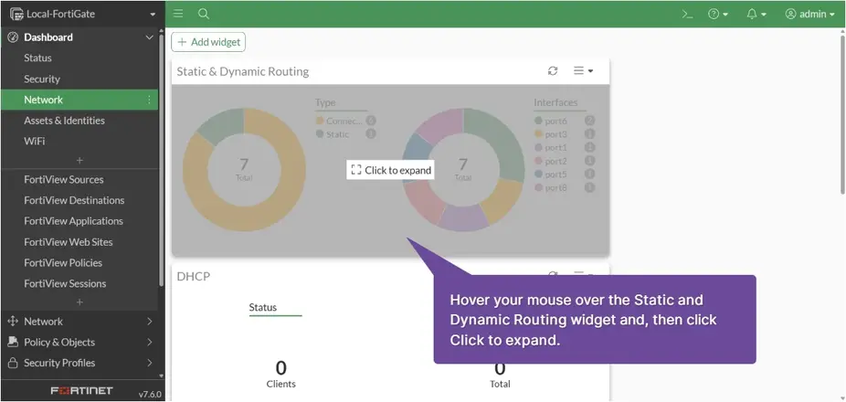
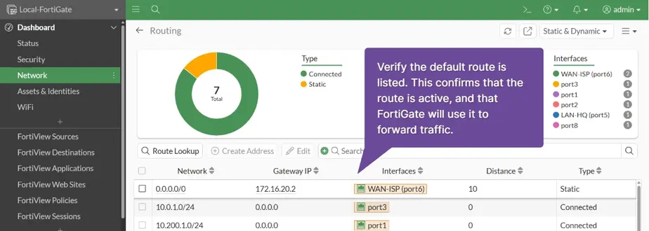
Dashboard > Network > Click to expand
Create a firewall address of the internal subnet
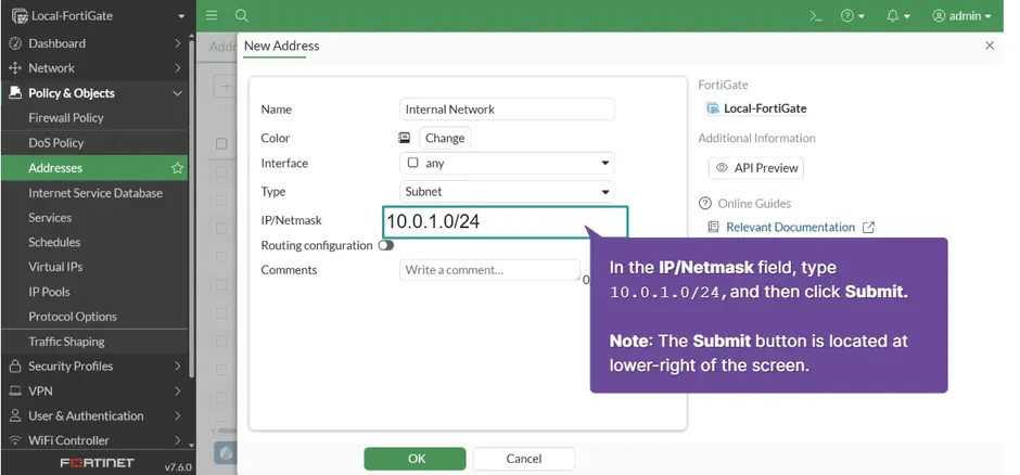
Policy & Objects > Addresses > Click Create New
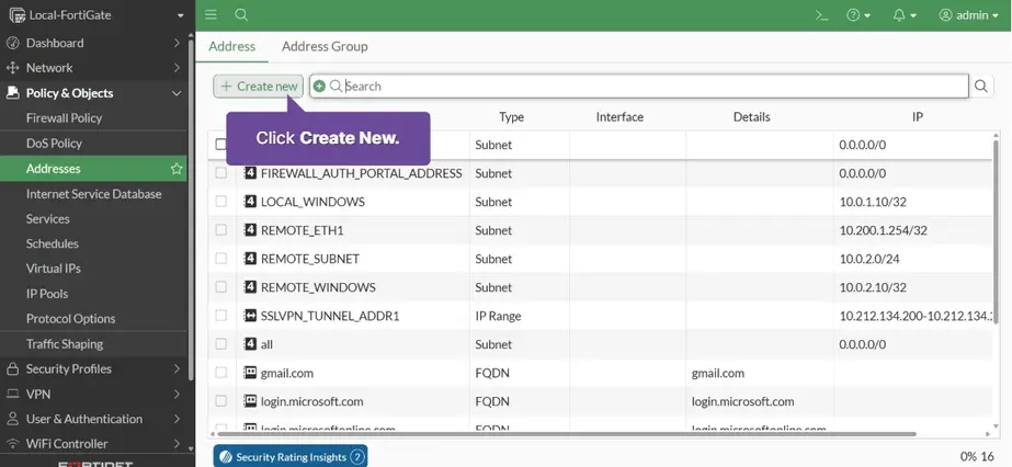
Name: Internal Network IP/Network: 10.0.1.0/24
Interface: port3 and press OK
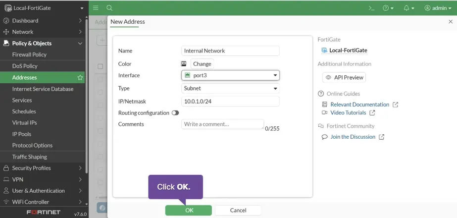
The firewall address of the internal subnet is created.
Configure the firewall policy
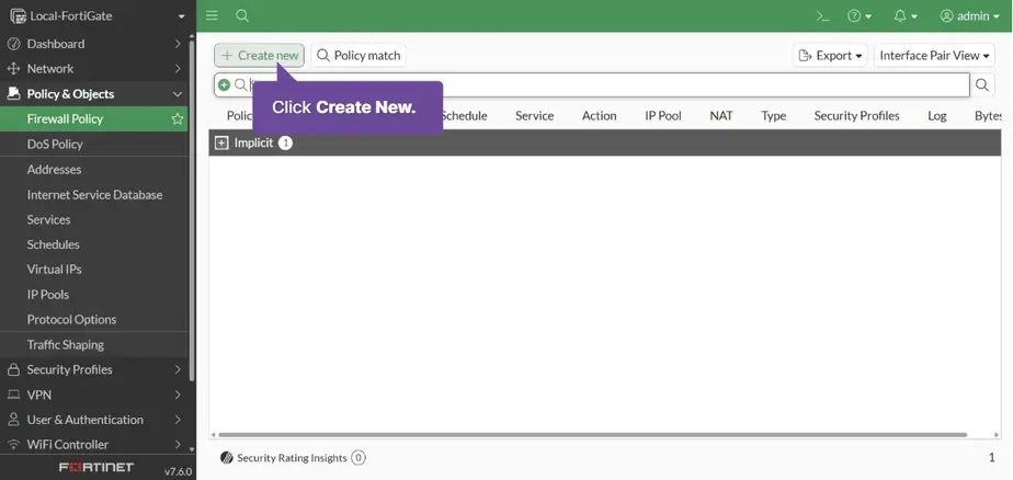
Policy & Objects > Firewall Policy > Click Create New
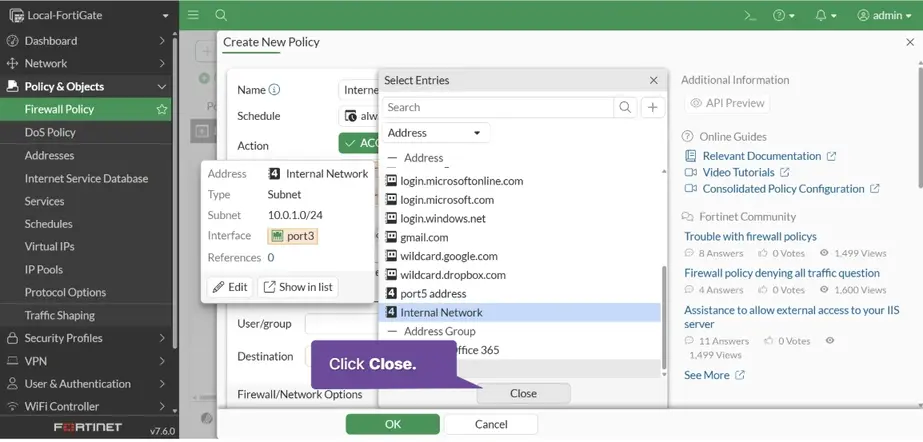
Name: Internal Access Incoming Interface: port3 Outgoing Interface: port1
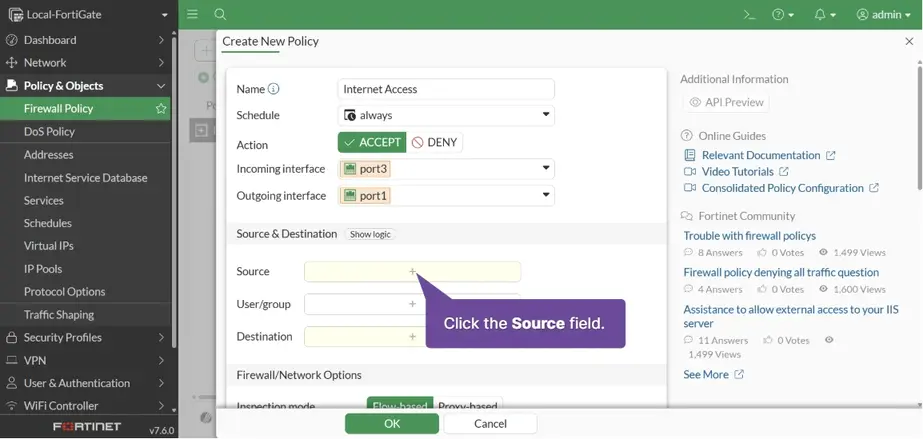
Click Source + > Select Internal Network > Click Close
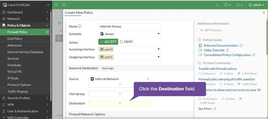
Destination + > Select all > Click Close
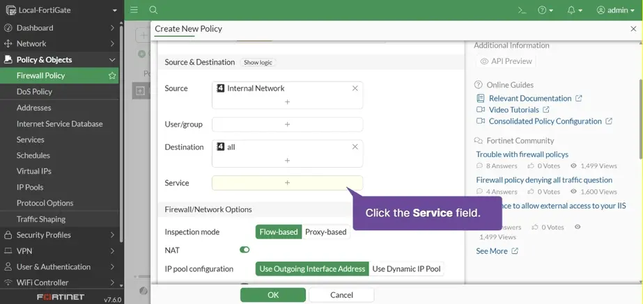
Service + > Select HTTP HTTPS DNS > Click Close
Enable NAT
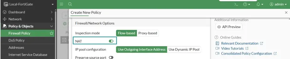
This is an outgoing traffic policy, and NAT is enabled. This allows FortiGate to translate the private address of the network device to the public IP address of the port1 interface.
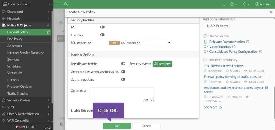
Log allowed traffic: All sessions and Click OK
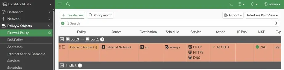
Firewall configuration complete!
Verify the firewall policy configuration
-
for test open https://www.fortinet.com
-
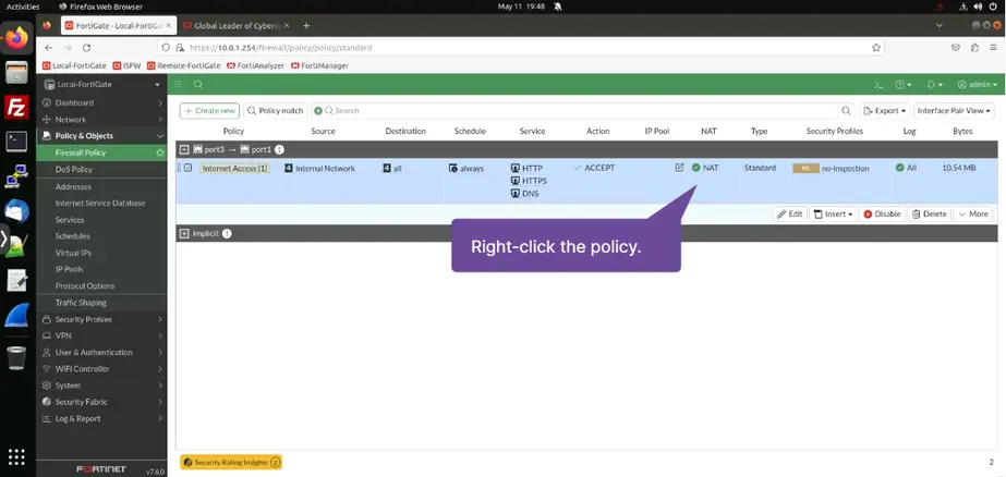
Policy & Objects > Firewall Policy > Right-click the policy
-
Click Show Matching Logs
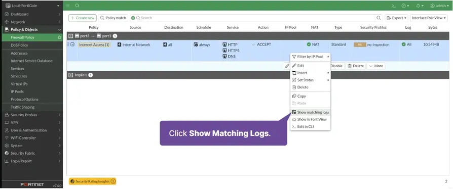
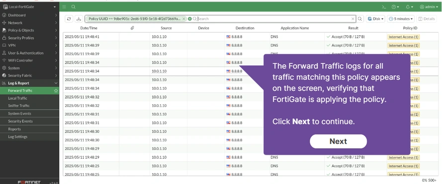
The Forward Traffic logs for all traffic matching this policy appears on the screen, verifying that FortiGate is applying the policy.
-
for test open cmd > telnet www.fortinet.com (its 23 port)
-
Policy & Objects > Firewall Policy > Right Click Implicit Deny policy > Click Show Matching Logs >
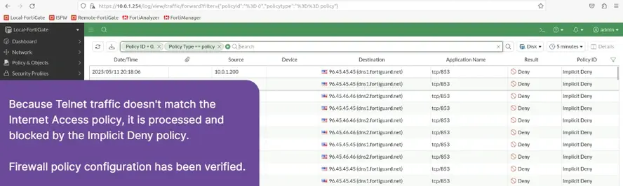
Because Telnet traffic doesn’t match the Internet Access policy, it is processed and blocked by the Implicit Deny policy.
Create a user account
User & Authentication > User Definition > Create New
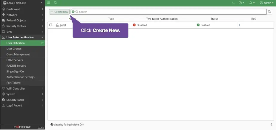
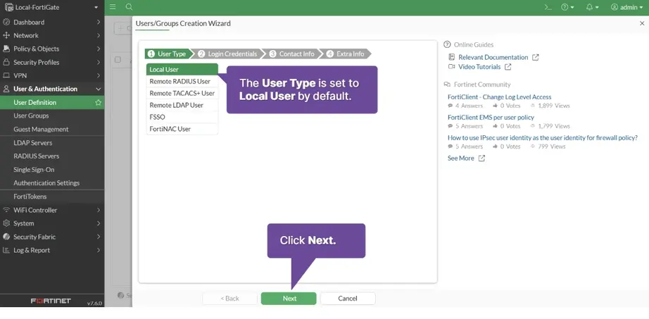
Username: fatima Password: password > Next
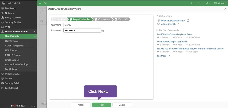
Click Next
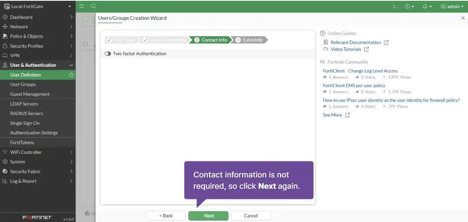
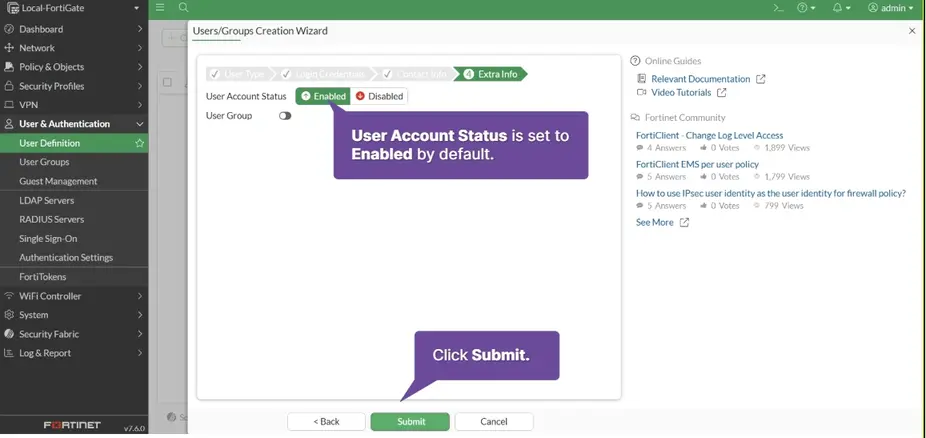
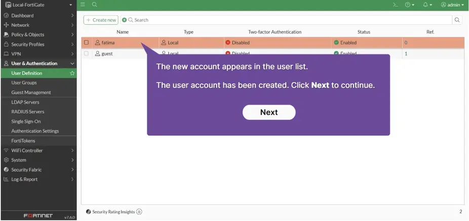
Configure remote authentication
User & Authentication > LDAP Servers > Create New
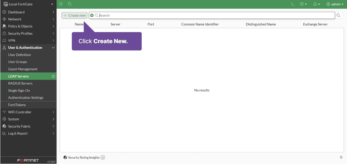
Name: RemoteAuthServer
Server IP/Name: 10.0.1.150
Server Port: 389
Common Name Indentifier: uid
Distinguished Name: ou=Training,dc=TrainingAD,dc=training,dc=lab.
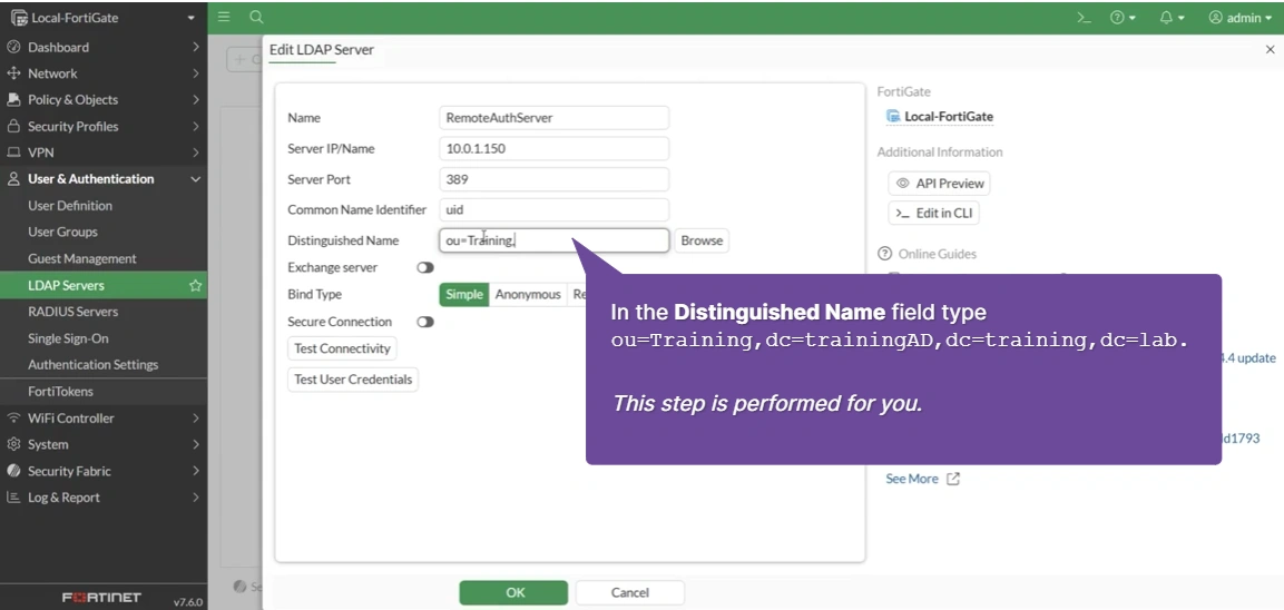 Bind Type:
 Regular
Username: uid=aduser1,ou=Training,dc=TrainingAD,dc=training,dc=lab
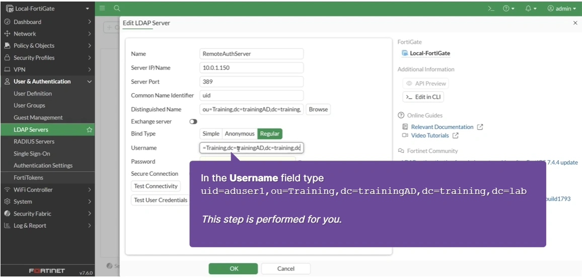
Password: Training! and Press Test Connectivity and OK
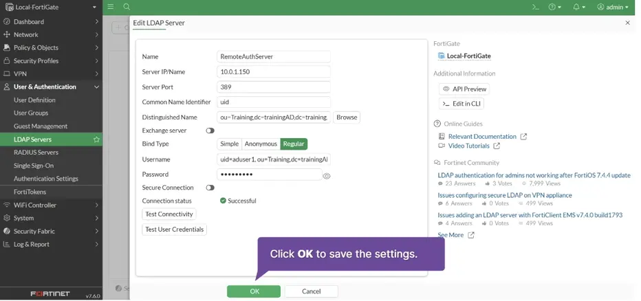

Remote authentication is configured
Create a user group
User & Authentication > Users Groups > Create New
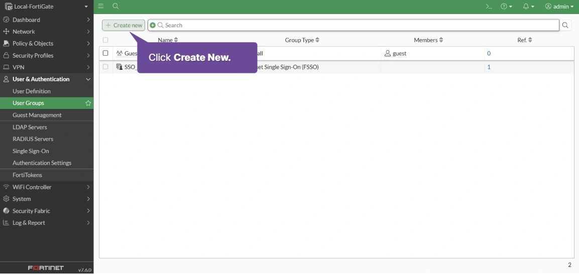
Name: sales Type: Firewall members: fatima
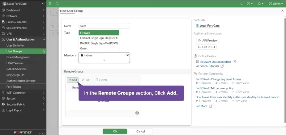
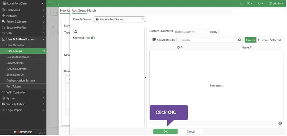
Remote Groups + Add > Remote Server: RemoteAuthServer > OK
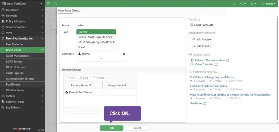
A user group created
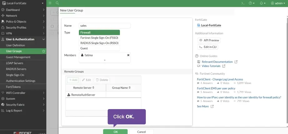
Click OK

Add authentication to the firewall policy
Policy & Objects > Firewall Policy > Internal Network > Edit
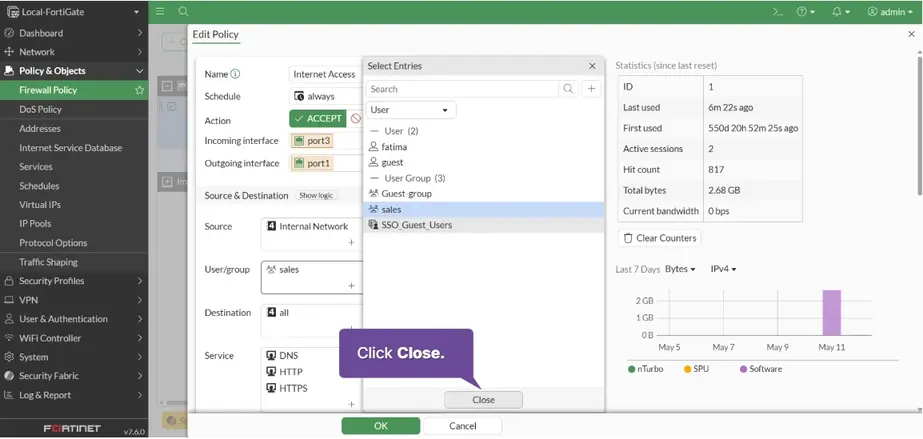
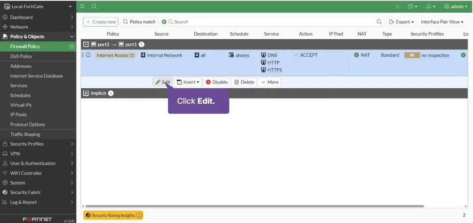 Open User/group:
 sales > close
 Click OK
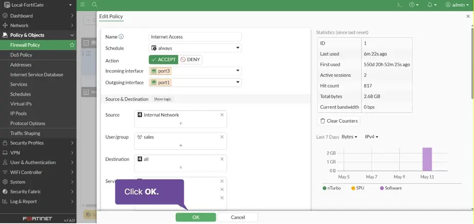
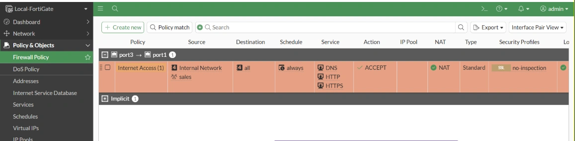
The sales group is now part of the firewall policy source.
Verify and monitor firewall authentication
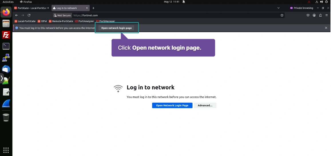
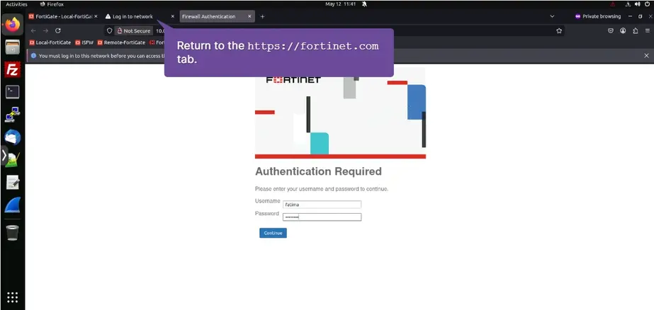
open website > Open network login page
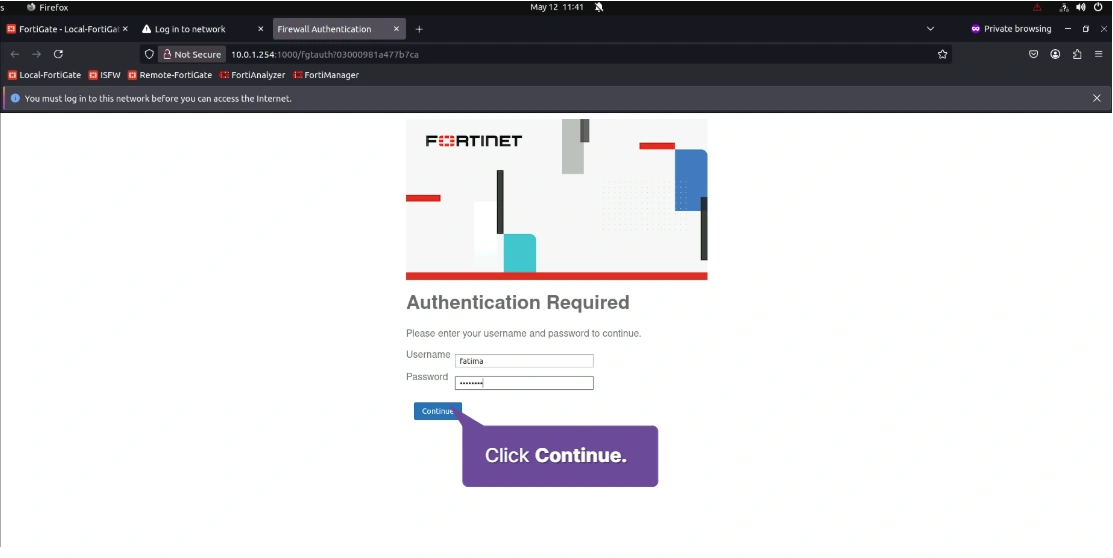
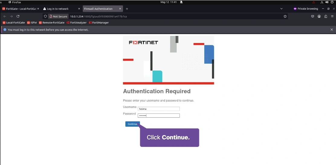
Username: fatima Password: password > Continue
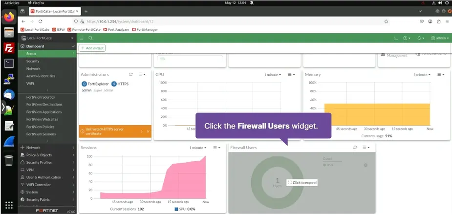
 Dashboard > Status > Firewall Users
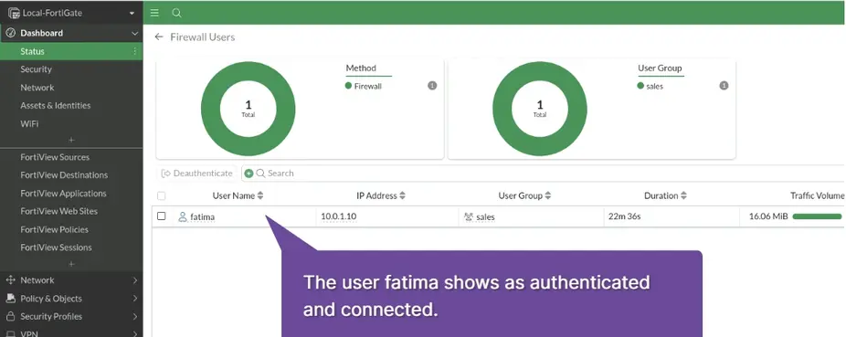
 The user fatima shows as authenticated and connected.
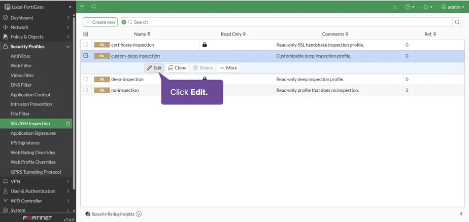
Apply SSL inspection
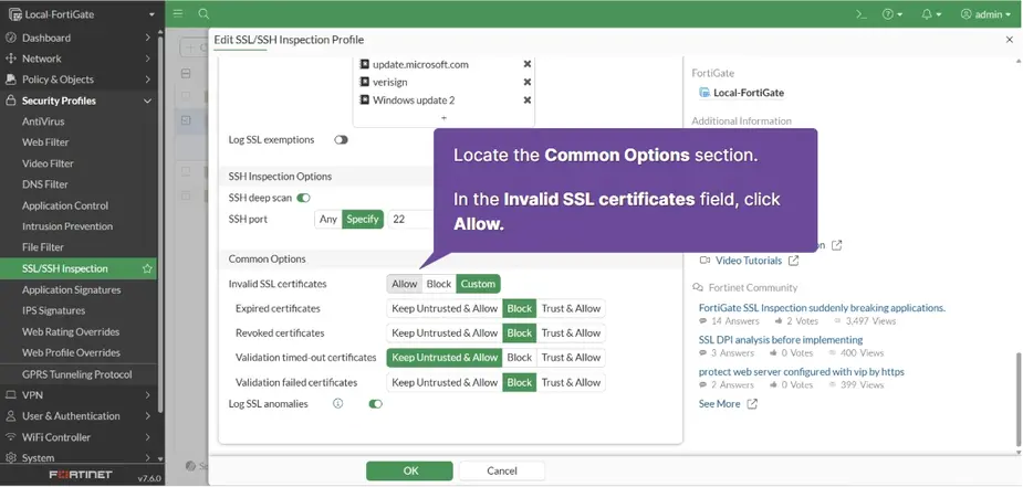
Securtity Profiles > SSL/SSH Inspection > Click on custom-deep-inspection > Click Edit
Invalid SSL certificates > Allow
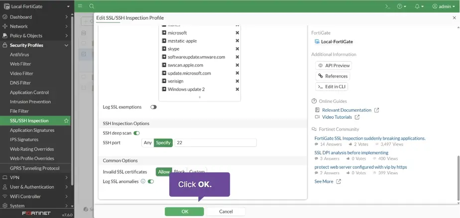
Click OK
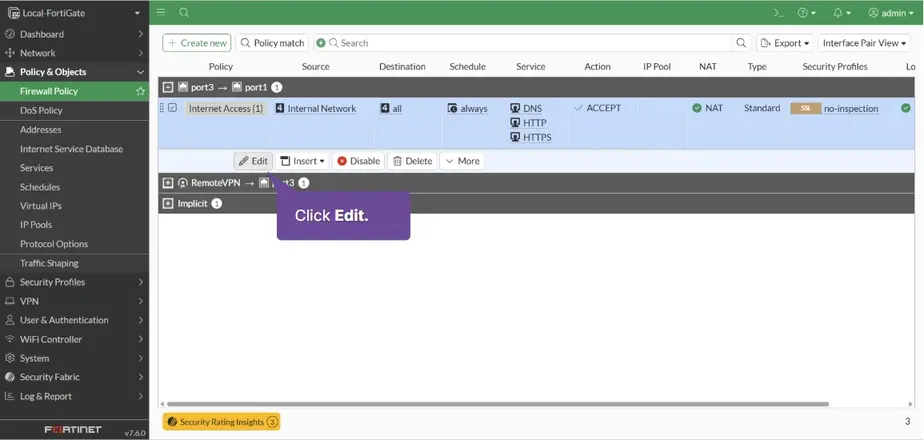
Policy & Objects > Firewall Policy > Internal Network > Edit
Web filter: default SSL inspection: custom-deep-inspection > OK > Warning OK
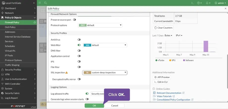
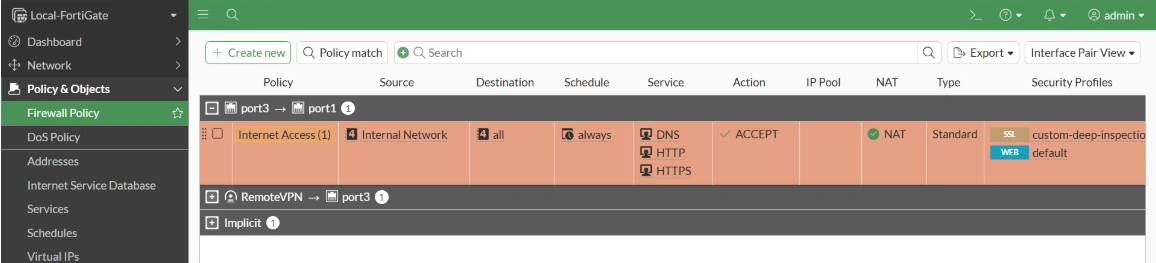
The security profiles are now applied to the firewall policy
in browser, go to https://google.com > Advanced > Aceept the Risk and Continue
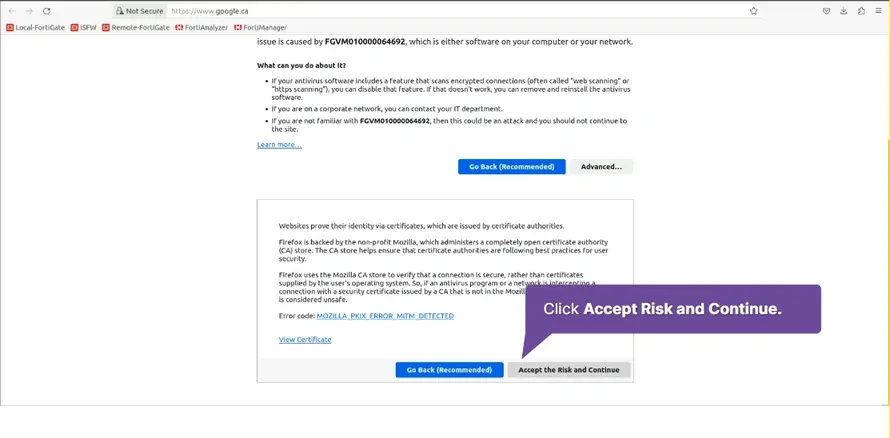
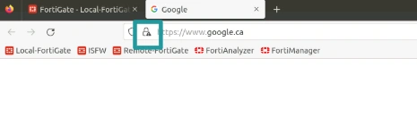
The lock with the warning indicates that you added a security exception.
Install the CA certificate to avoid certificate warnings
Securtity Profiles > SSL/SSH Inspection > Click on custom-deep-inspection > Click Edit
CA certificate Download Fortinet_CA_SSL
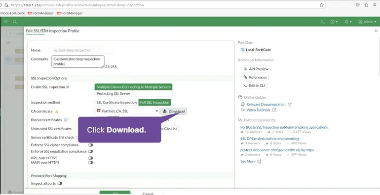
and install it
Create an antivirus profile
Security Profiles > AntiVirus > default > Edit
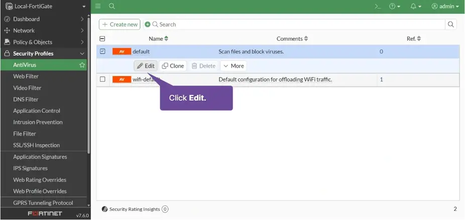
Use FortiGuard outberak prevention database [X] > OK

The default antivirus profile edit is complete.
Apply antivirus to a firewall policy
Policy & Objects > Firewall Policy > Internal Network > Edit
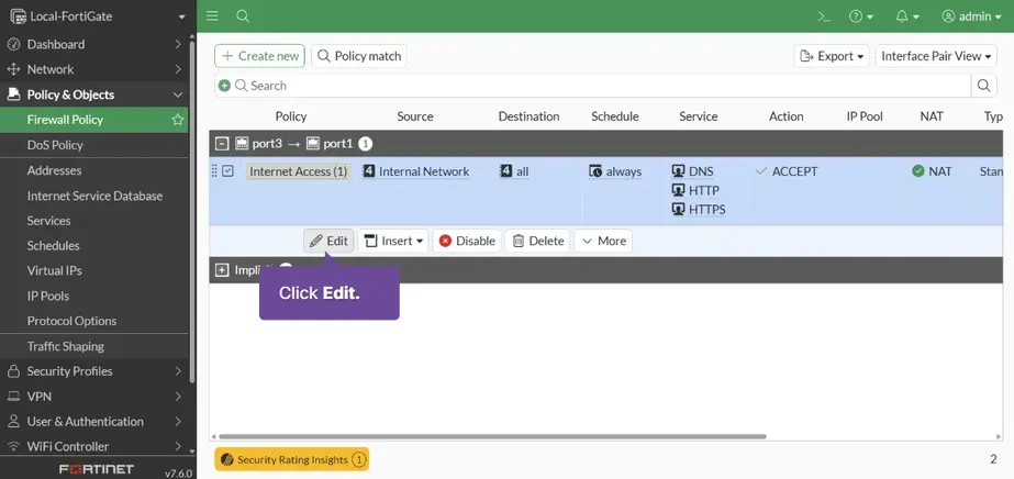
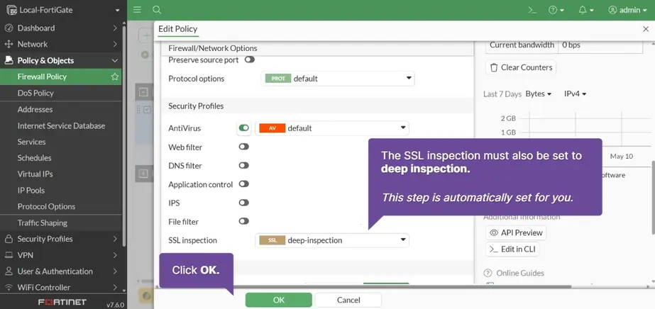
Policy & Objects > Firewall Policy > Internet Access > Edit
Antivirus[V] default > SSL Inspection deep-inspection > OK
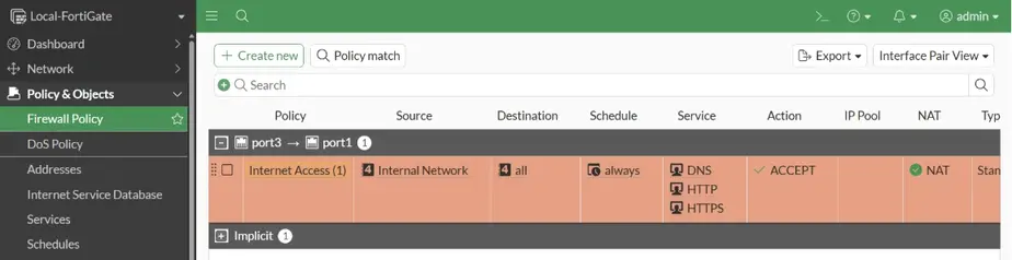
The security profile is now applied to the firewall policy
Verify antivirus
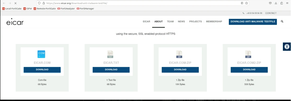
Type https://www.eicar.org/download-anti-malware-testfile
download Com-file
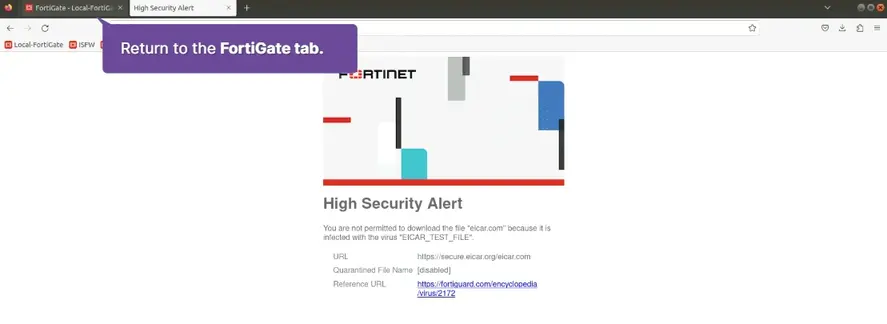
Log & Report > Security Events > AntiVirus
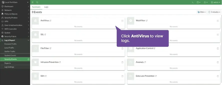
One or more EICAR_TEST_FILE entries appear, with the Action show as Blocked.

Antivirus inspection is verified.
Configure Web Filter on FortiGate
Ensure that FortiGate has valid FortiGuard security subscription license
Status > Webfilter [see status]
Identify how the FortiGuard service categorizes specific websites
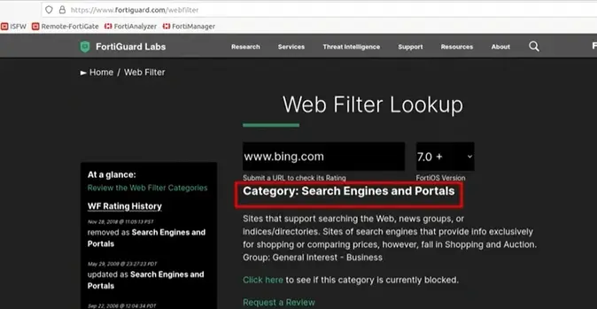
Configure a web filtering profile to use FortiGuard category-based filters
Security Profiles > Web filter > default > edit
Social Networking: block > OK
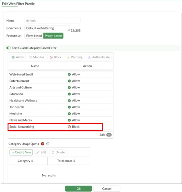
Apply the web filter security profile to a firewall policy
-
Policy & Objects > Firewall Policy > Full Access > edit
-
Web filter:
default, SSL Inspectioncustom-deep-inspection, Log allowed traffic [Security events] > OK
Test the configured actions for FortiGuard category-based filters and examine logs
-
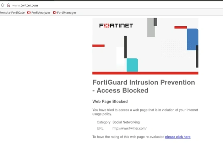
type site
-
Log & Report > Security Events > Web Filter > logs
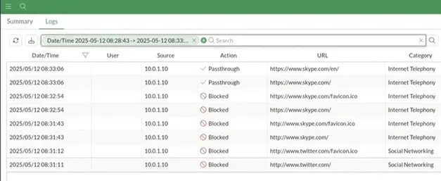
Configure Authenticate cation for a FortiGuard Category Filter
-
Security Profiles > Web Filter > default > edit
-
FortiGuard Category Based Filter > Authenticate > Warning Interval :
5 minute(s)Selected User Groups:Ovveride_Permissions> OK > OK -
User & Authentication > User Definition > + Create New > Local User > Next > Username
studentPasswordpassword> Next > Next > User Group [x]Overide_Permissions> Submit
Test the Authenticate action and examine logs
type in browser
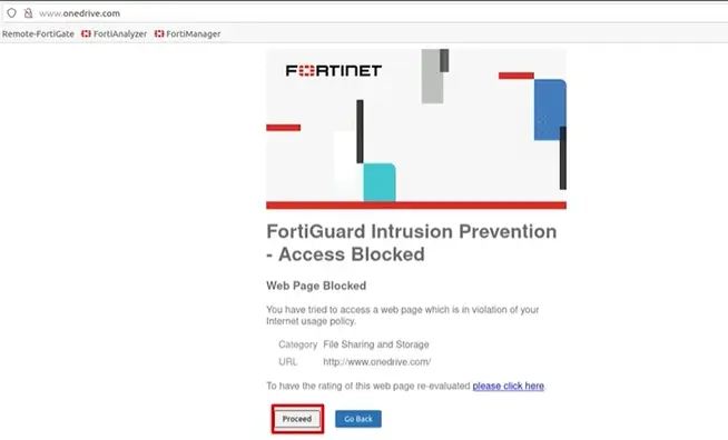
username & password
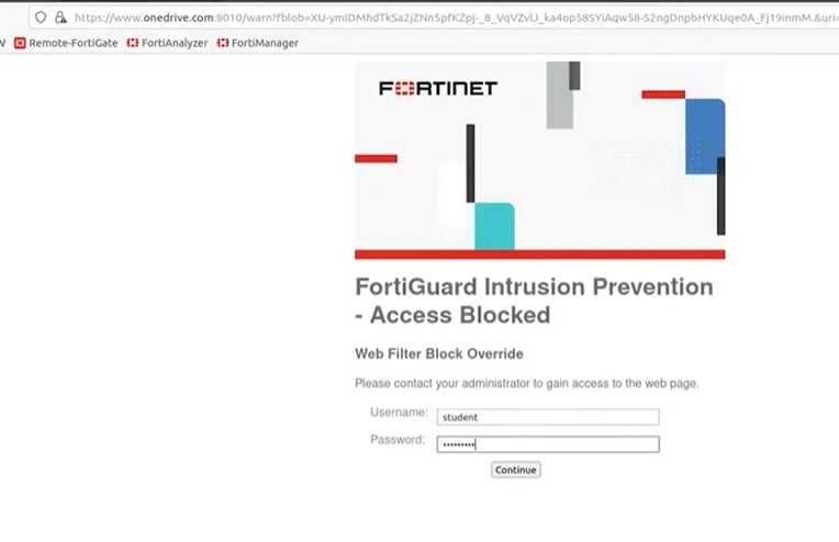
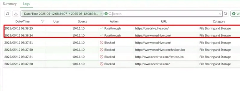
Create a Custom IPS sensor
Security Profiles > Intrusion Prevention > Create New
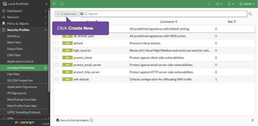
Name: Radius_Signatures_Sensor > + Create New
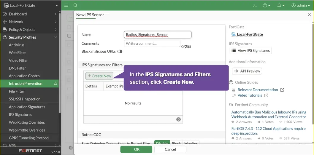
Type: Signature > Action: Block > Type Radius > Search Icon
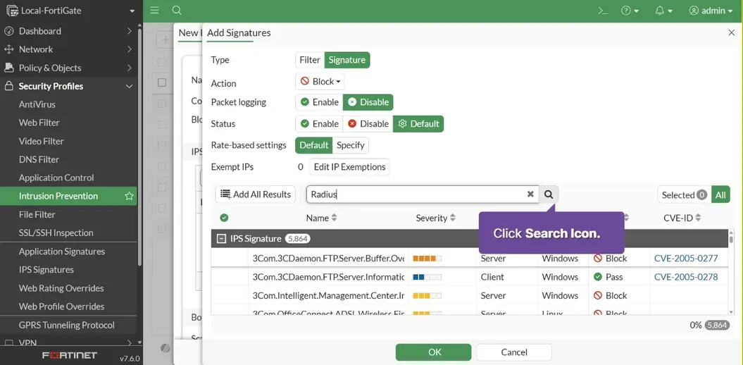
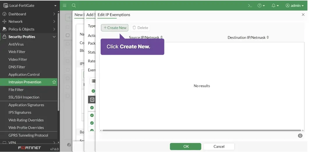
Add All Results > Edit IP Exemptions
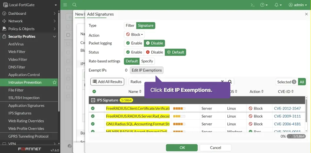
Click Create New
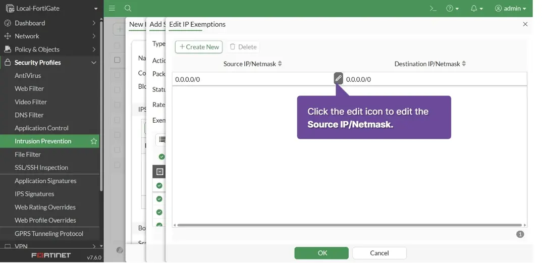
Click Source IP/Netmask
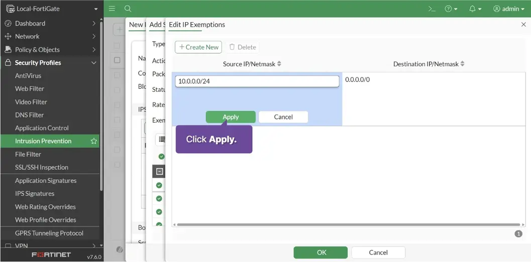
Type 10.0.0.0/24 > Apply > OK
Click OK
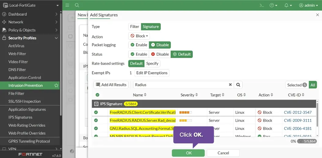
Click OK
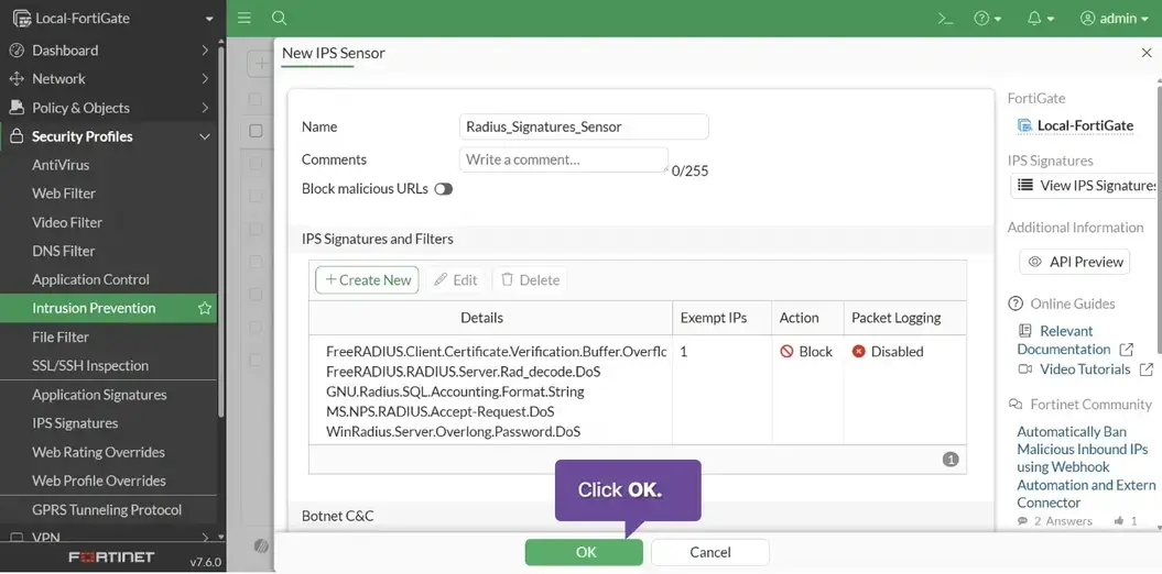
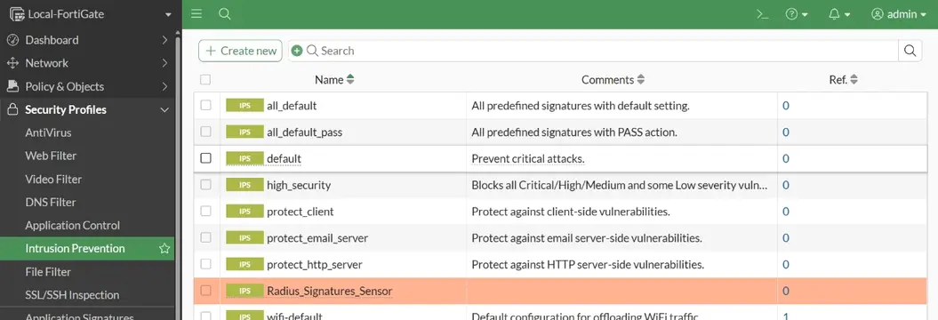
This sensor is ready to be applied to a firewall policy
Configure application control
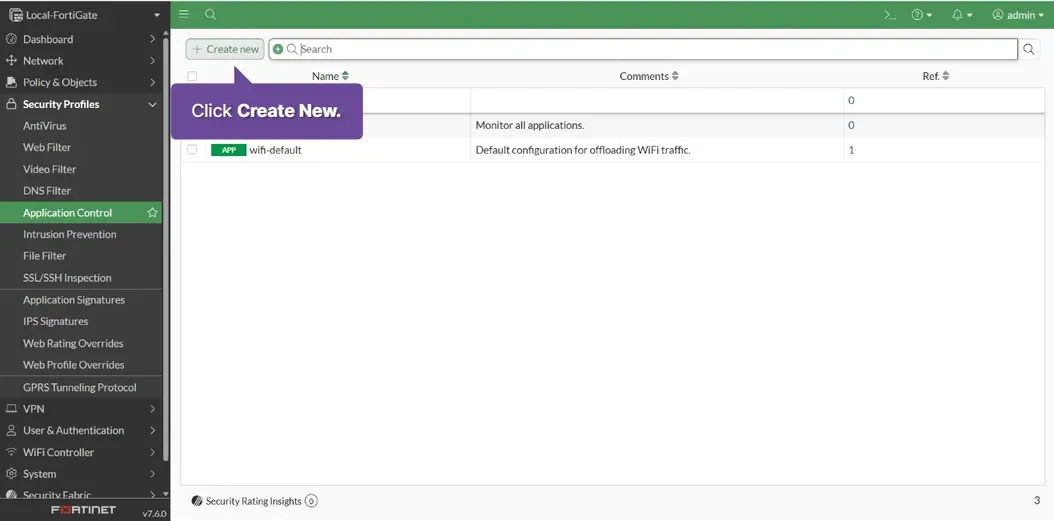
Security Profiles > Application Control > Create New
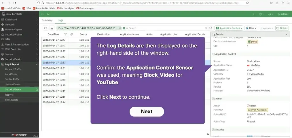
Name:Block_Video
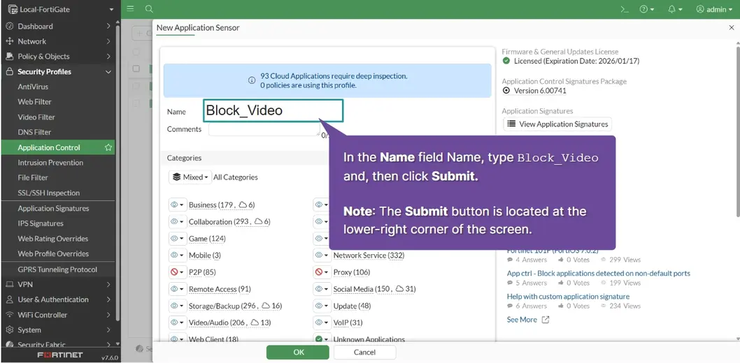
Video/Audio: Block
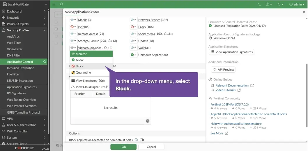
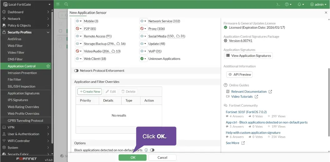
Click OK
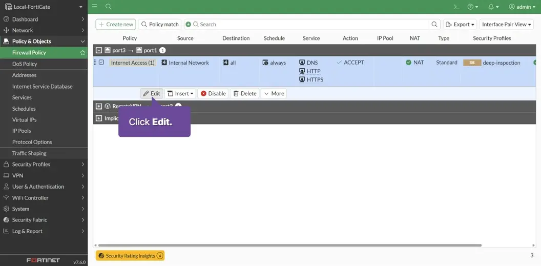
Policy & Objects > Firewall Policy > Internet Access > Edit
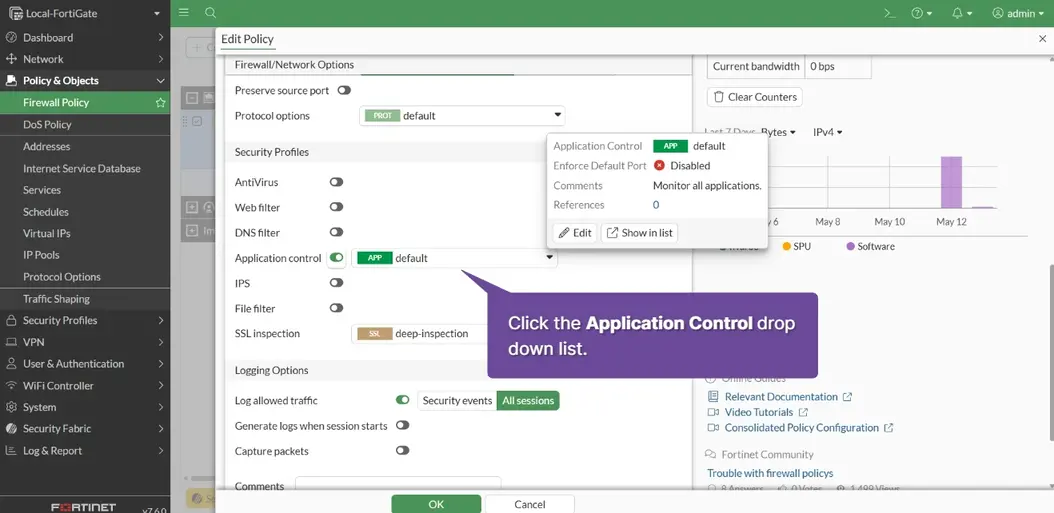
Application control: [x] Block_Video
Click OK
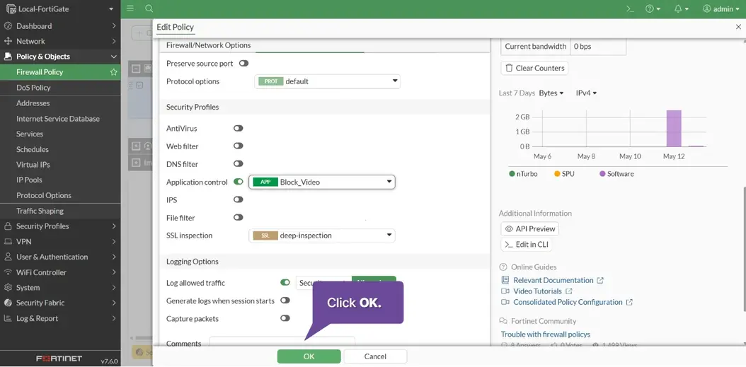
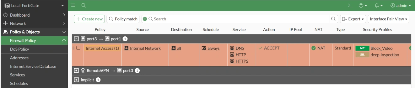
The application control profile is configured.
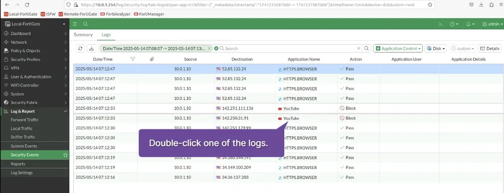
Monitor application control
Type: www.youtube.com
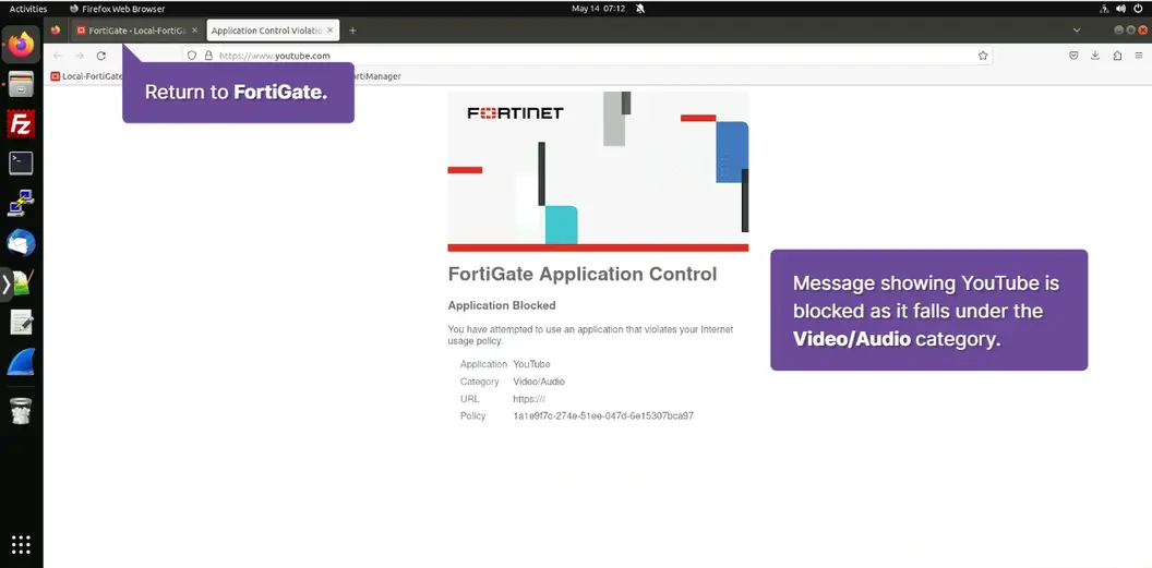
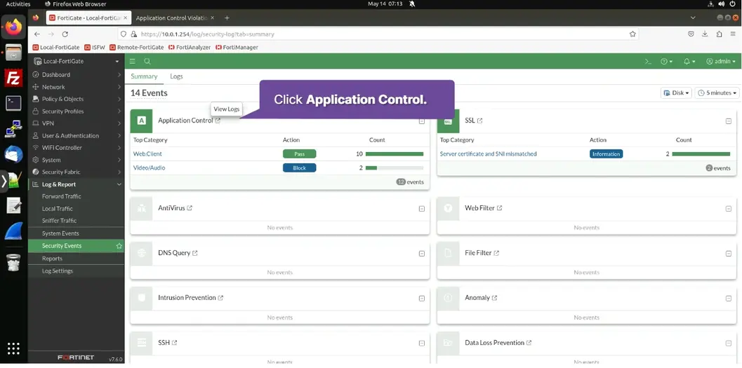
Log & Report > Security Events > Double-Click Application Control
Comfigure and test a site-to-site IPsec VPN
Create the IPSec VPN using the VPN wizard
-
VPN > VPN Wizard > Tunnel name:
HQ-to-BranchSelect a Template [x][Site to Site] > Begin -
Remote Site, IP/FQDN
10.200.3.1Remote site subnet can acess VPN10.0.2.0/24>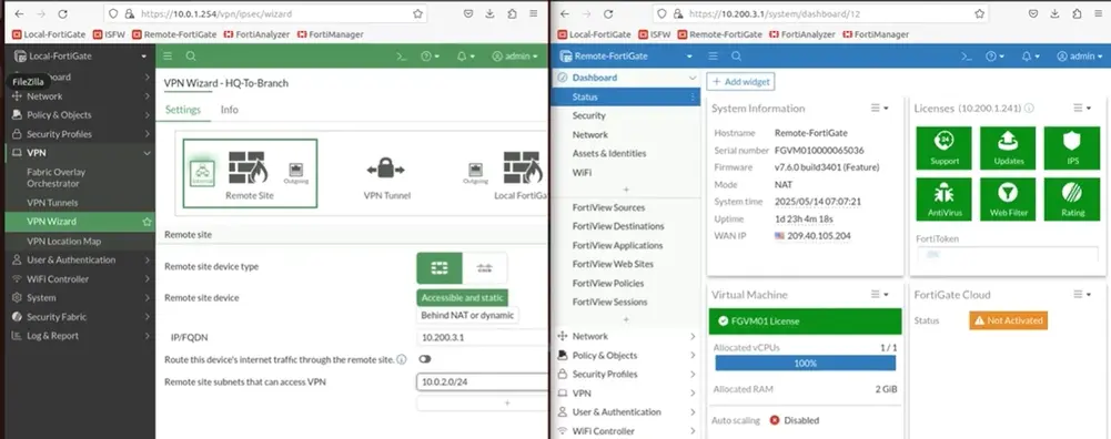
-
VPN Tunnel, Pre-shared key:
password, Next > -
Outgoing interface that binds to tunnel
port1local interfaceport3local subnets that can access VPN10.0.1.0/24, Next >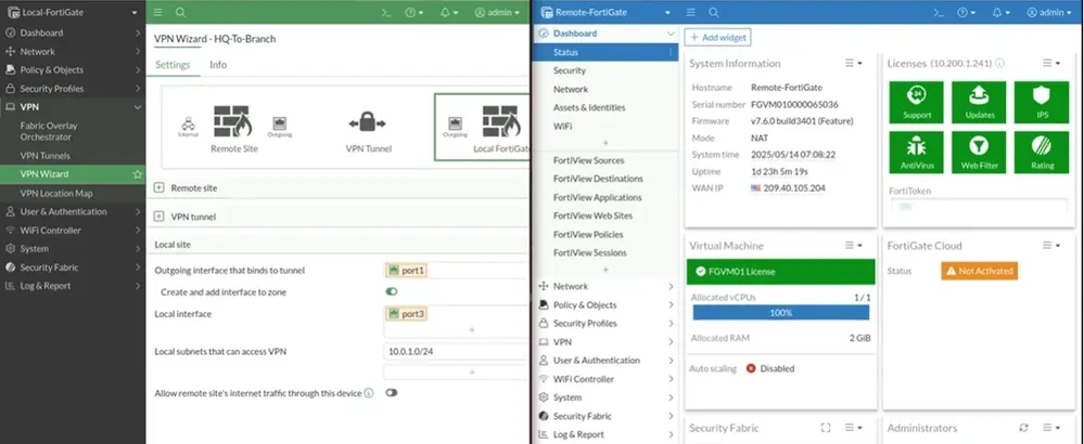
-
Submit
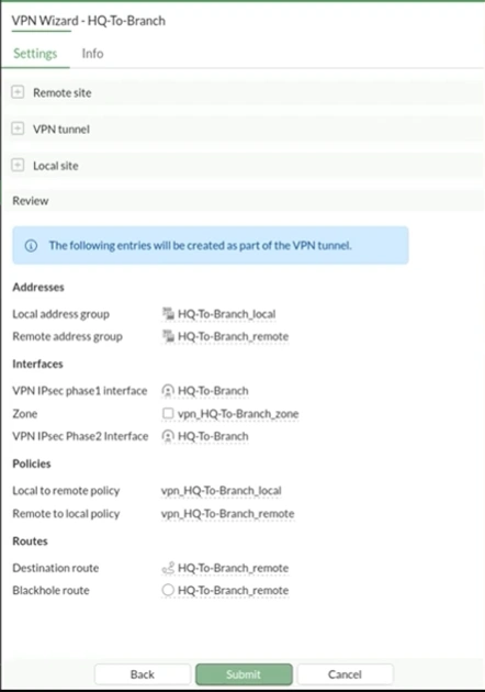
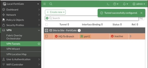
-
VPN > VPN Wizard > Tunnel name:
Branch-to-HQSelect a Template [x][Site to Site] > Begin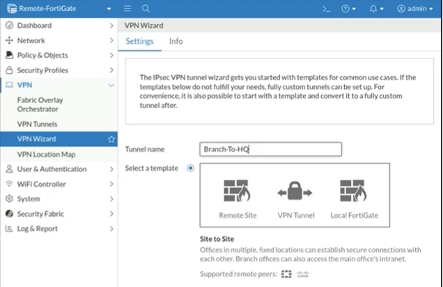
-
Remote Site, IP/FQDN
10.200.1.1Remote site subnet can acess VPN10.0.1.0/24> -
VPN Tunnel, Pre-shared key:
password, Next > -
Outgoing interface that binds to tunnel
port4, local interfaceport6, local subnets that can access VPN10.0.1.0/24, Next > -
Submit
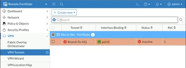
Test the site-to site IPsec VPN
- cmd > ping 10.0.2.10
VPN > VPN Tunnels >
Configure Fortigate for remote access IPsec VPN
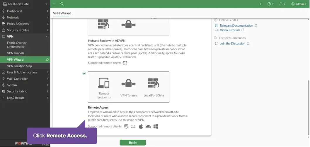
VPN > VPN Wizard > Click Remote Access
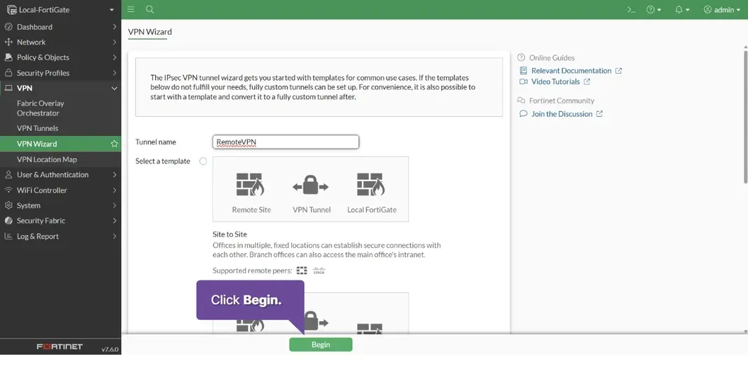
Tunnel Name: RemoteVPN > Click Begin
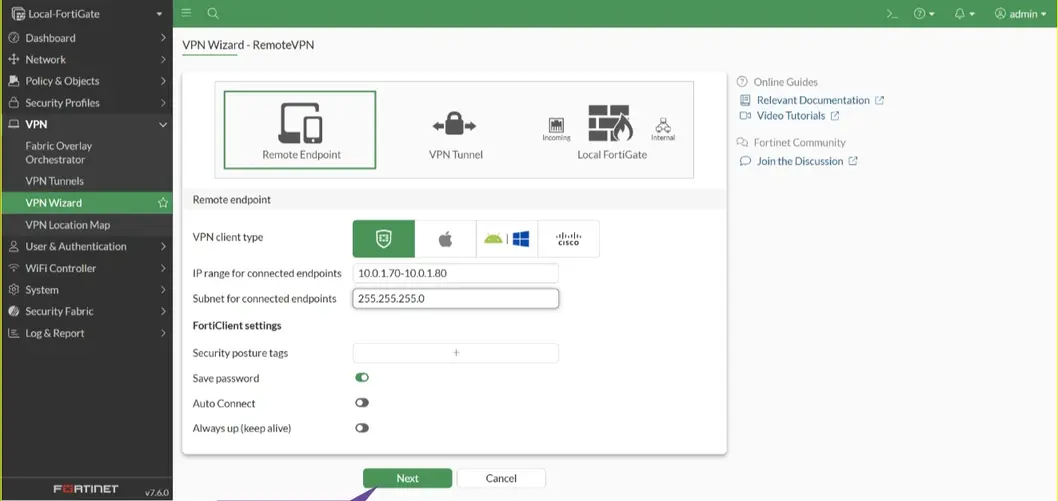
IP Range for connected endpoints 10.0.0.70-10.0.0.80 Subnet 255.255.255.0 > Next
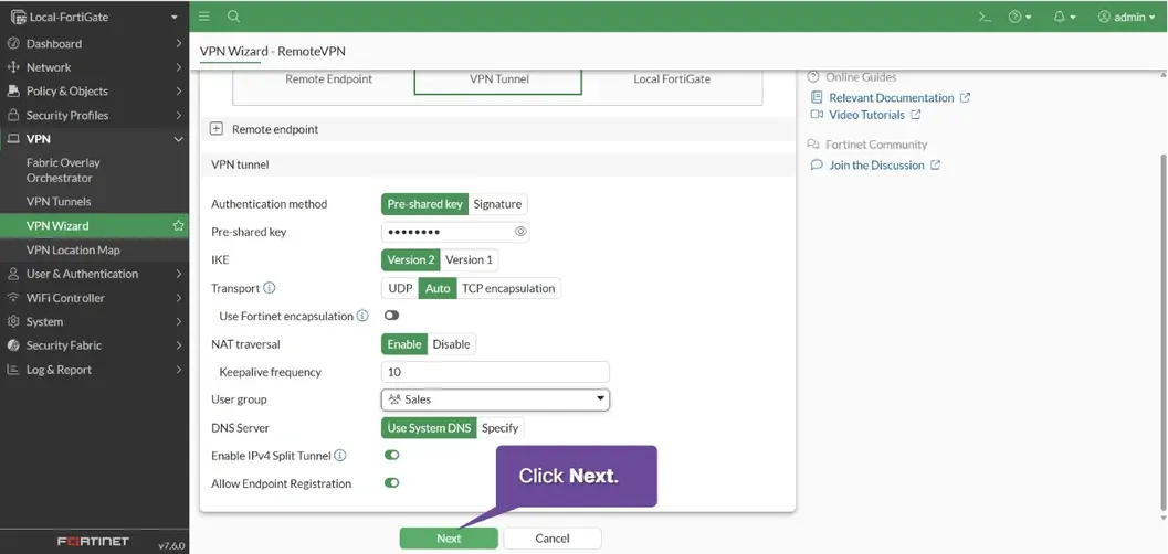
Pre-shared key password User group Sales > Next
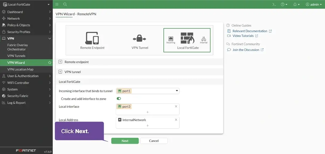
Incoming Interface that binds to tunnel port1 Local Interface port3 Local Address InternalNetwork > Next
Click Submit
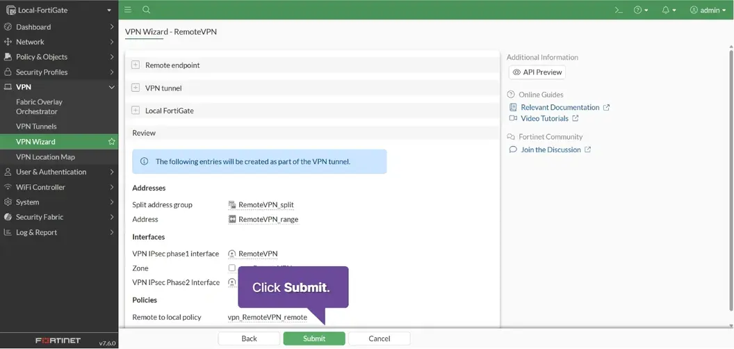

VPN has been set up
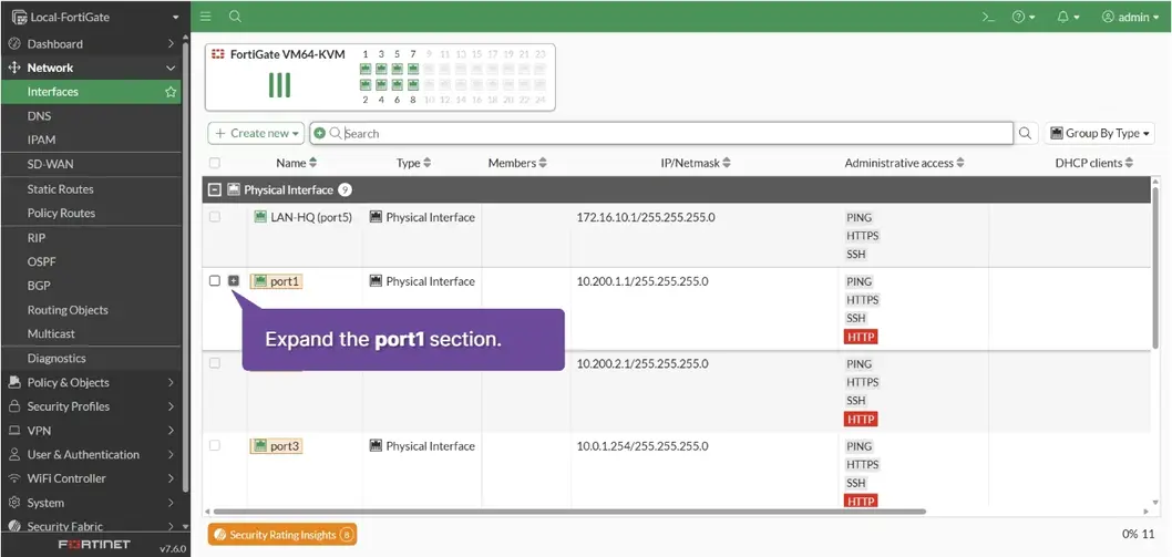
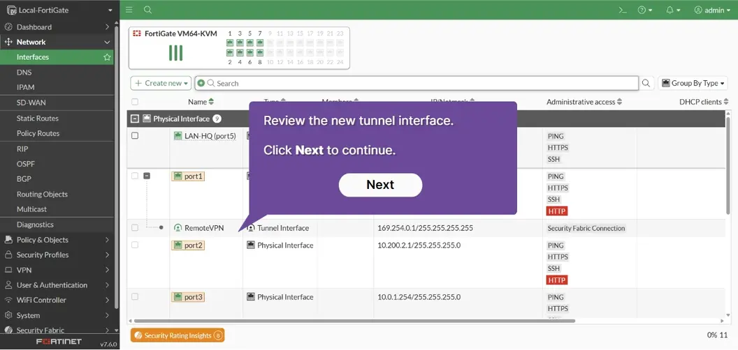
Network > Interfaces > +
Policy & Objects > Firewall Policy

Examine the entry with the name containing the string RemoteVPN
Policy & Objects > Addresses > Search: romotevpn
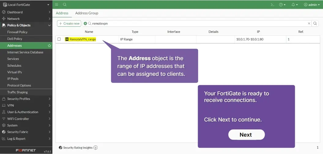
Configure and Test SSL VPN with FortiGate
VPN > SSL-VPN Portals > Double-Click full-access >
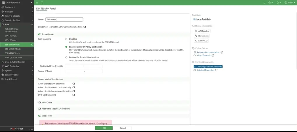
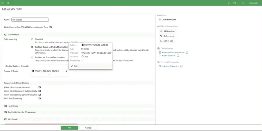 Click OK
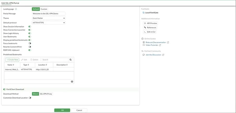
Configure VPN SSL settings
-
SSL-VPN status
EnableListen on Port443Service Certificate:Fortinet_Factory> + Create New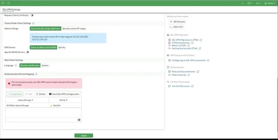
-
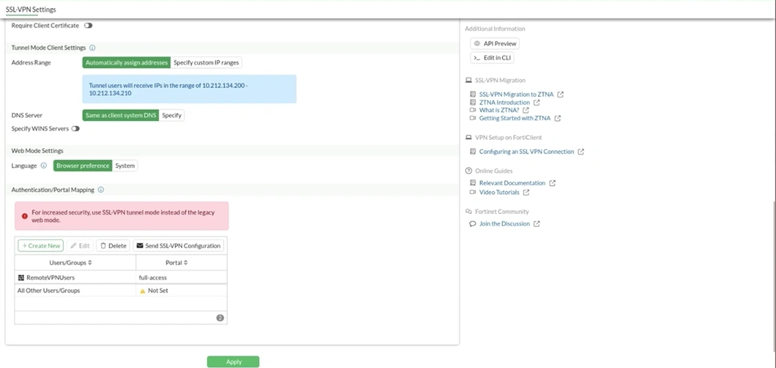
+ Create New > UserGroups
RemoteVpnUsersPortalFull-access -
Apply
Configure Policy Firewall
-
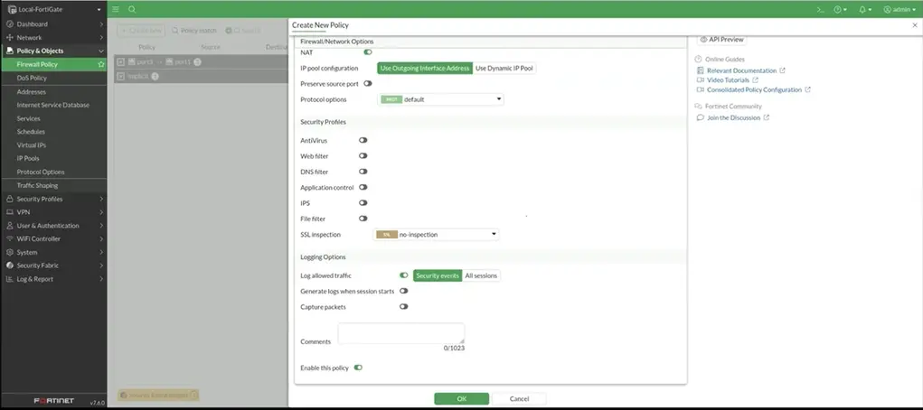
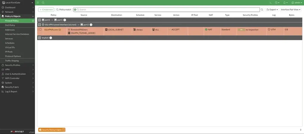
Policy & Objects > Firewall Policy > Create New
Name: `SSLVPNACCESS`
Incoming interface: `SSLVPN tunnel Interface (ssl root)`
Outgoing interface: `port3`
Source:  `SSLVPN_TUNNEL_ADDR1`
Usergroup: `RemoteVPNUsers`
Destination: `LOCAL_SUBNET`
Service: `ALL`
OK >
Backup up the configuration and performing a filmwware upgrade
Click Admin > Configuration > Backup > OK
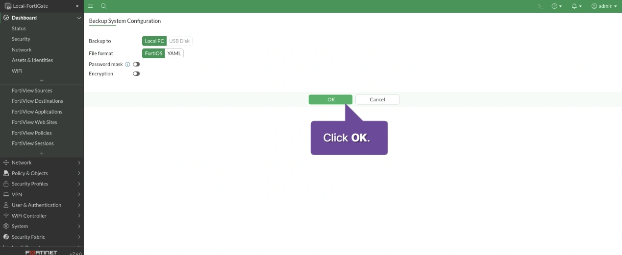
Now that you have a configuration backup, you can safely upgrade your FortiGate firmware. It is a best practice to backup your configuration before you start an upgrade, or you can do it during the upgrade. This simulation shows you how to do both.
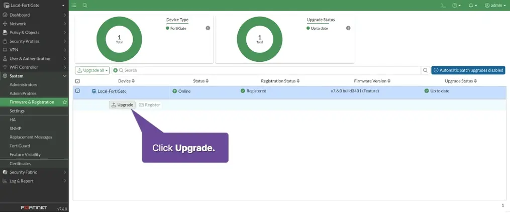
Click Admin > System > Firmware & Registration > local-FortiGate > Upgrade
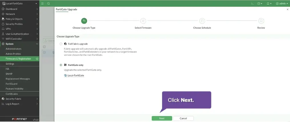
[x] FortiGate Only > Next >
File Upload > Upload File > Select file > Next
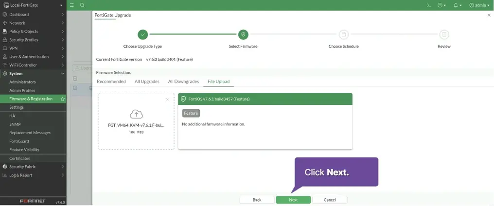
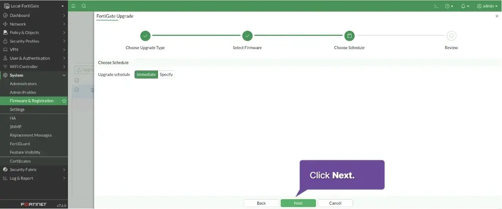
Click Next
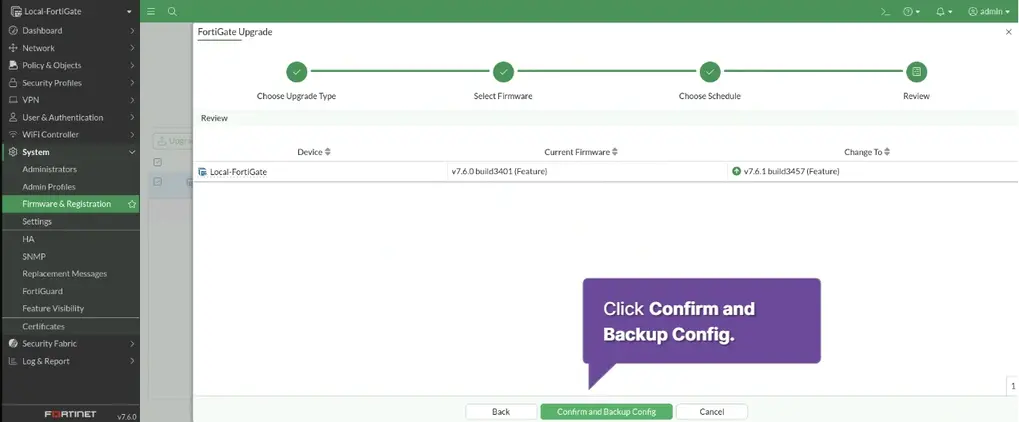
Click Confirm and Backup config > System will reboot upon proceeding Are you sure you want to continue? > Yes
The system will be restart with the new firmware installed.
Examining traffic logs
Log & Report > Forward Traffic > Click on log
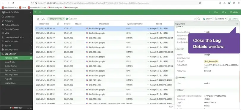
Scroll down the Log Details window to view the Action section.
Hover your mouse over the value next to Policy ID to see details about the firewall policy that generated this log.
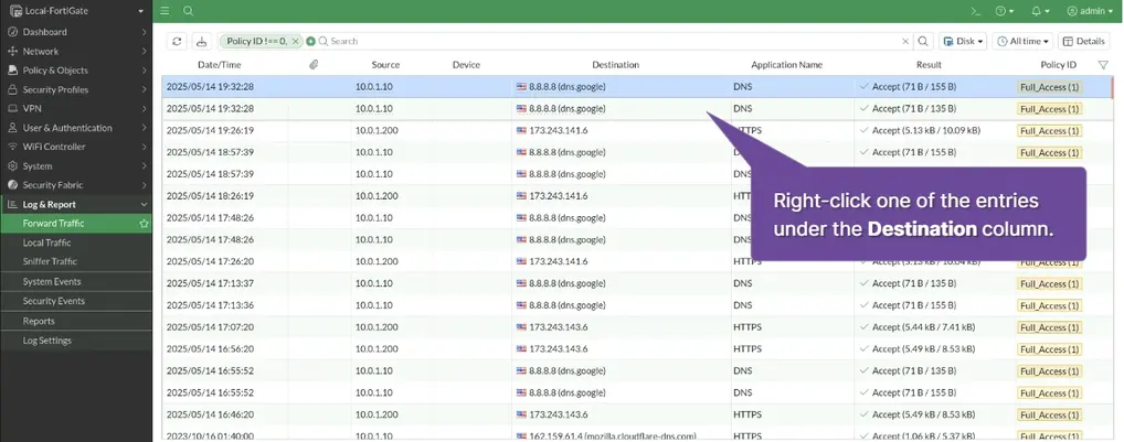
Right Click on Destination
Configure and Test Fortinet Security Fabric
Verify the FortiAnalyzer configuration
Device Manager >
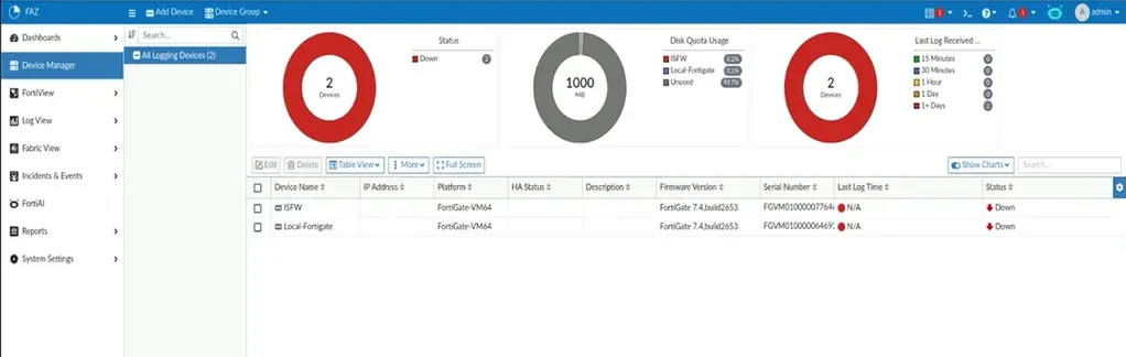
Status Down
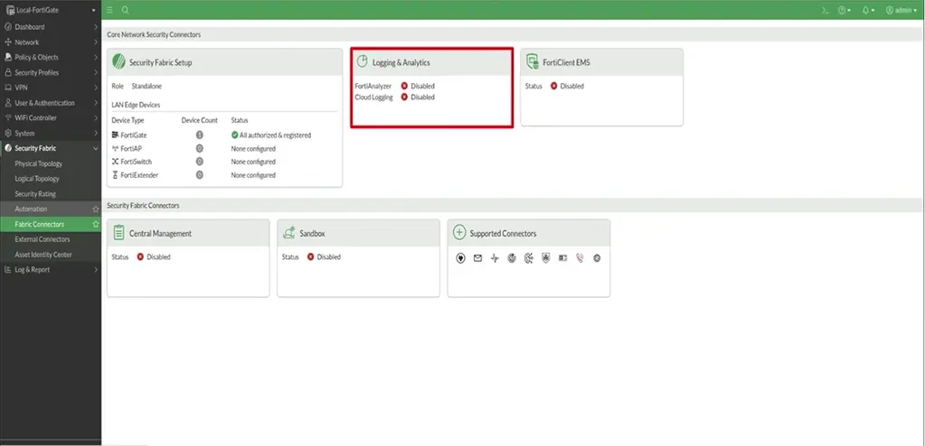
Configure Logging on Local-FortiGate
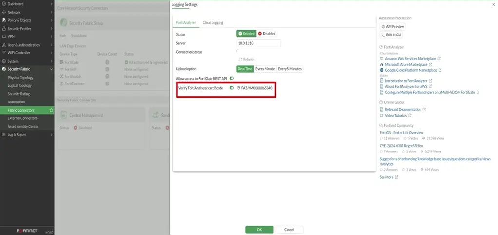
Security Fabric > Fabric Connectors > Double-Click Logging & Analytics > Edit
Status: Enabled Server: 10.0.1.210 Upload option [Real Time] > OK > Accept
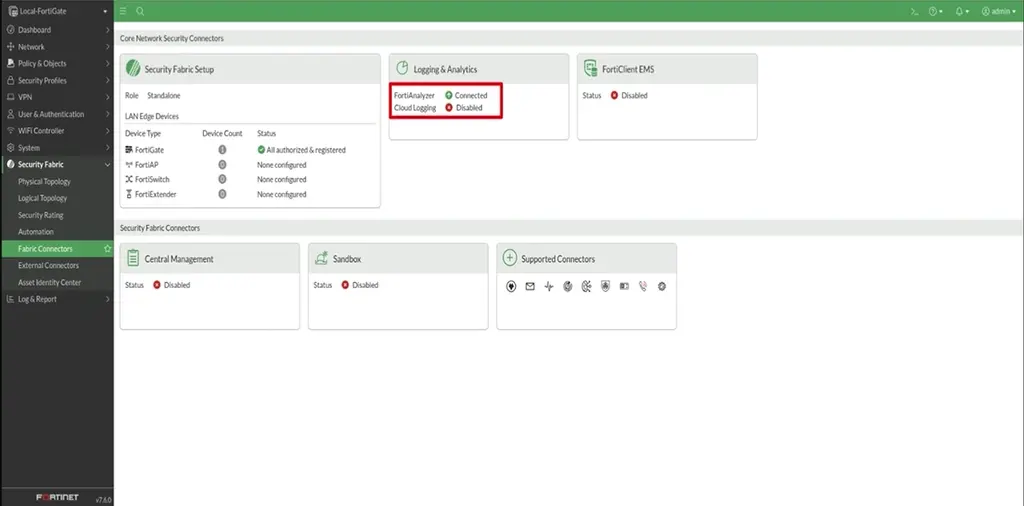
Configure Local-FortiGate for the Security Fabric and make it Root firewall
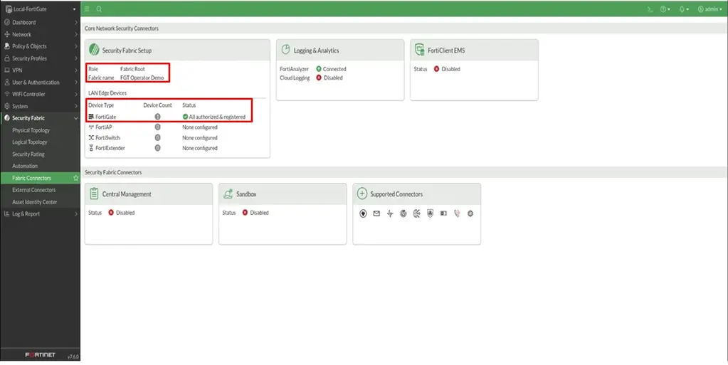
Security Fabric > Fabric Connectors > Double-Click > Secure Fabric Setup > Select Server as Fabric Root
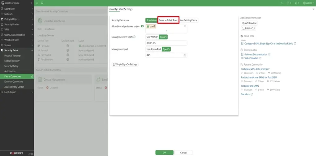
Allow other Security Fabric device to join > + > port3 > edit >
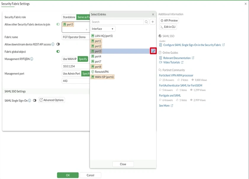
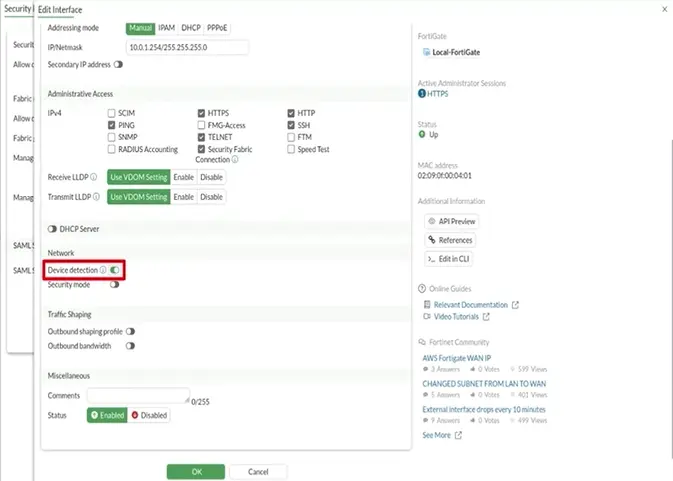
Security Fabric [x] Device detection [x] > OK > OK > Close
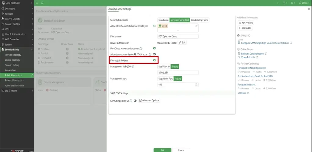
Fabric Name: FGT Operator Demo Fabric global obkect [x]
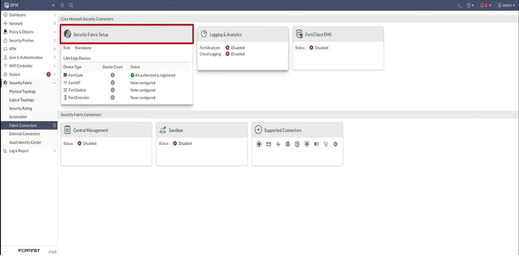
Add Task ISFW to the Security Fabric
Security Fabric > Fabric Connectors > Double-Click > Secure Fabric Setup >
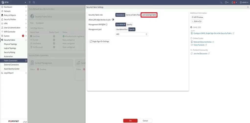
Join Existing Fabric > Allow other Security Fabric devices to join [x] > [+]
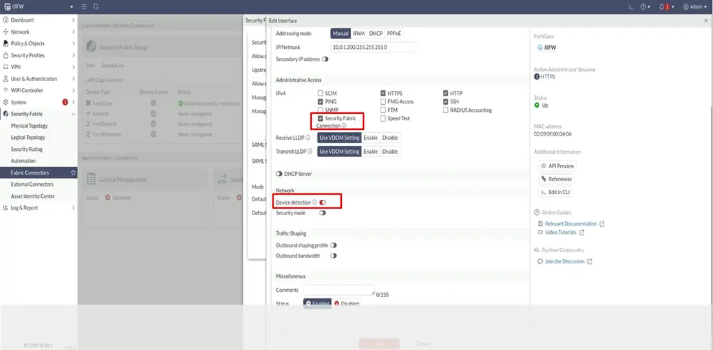
port1 > edit >
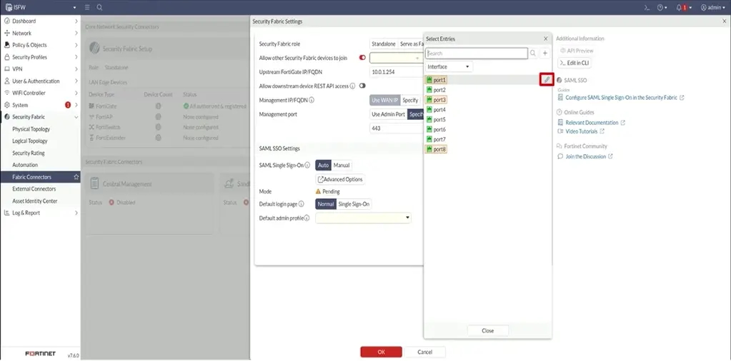
Security Fabric [x] Device detection [x] > OK > OK > Close
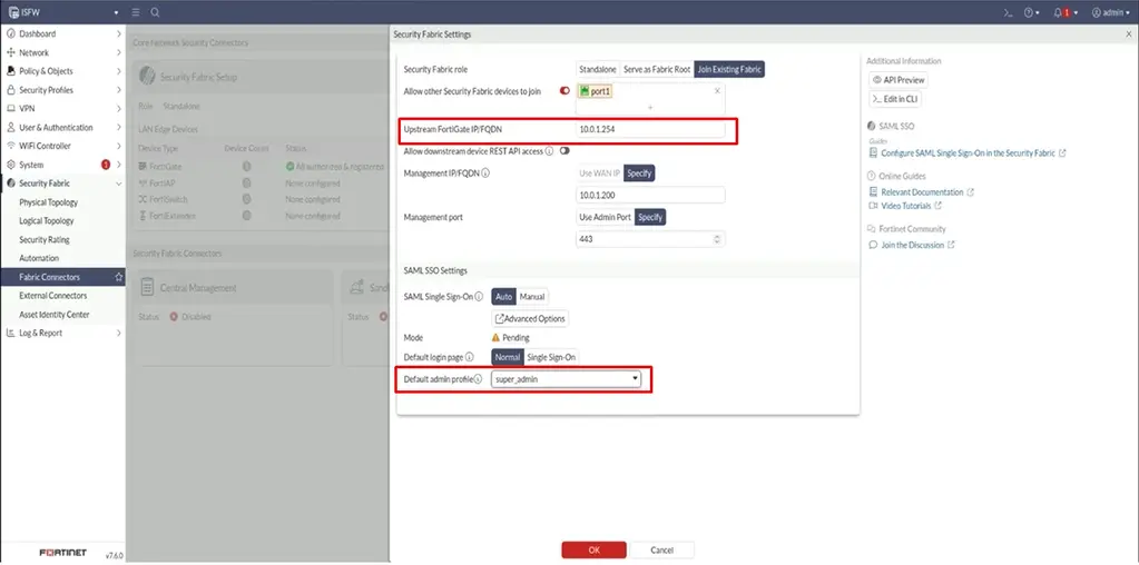
Upsteam FortiGate IP/FQDN 10.0.1.254 Management IP/FQDN [Specify] 10.0.1.200 Default admin profile super_admin > OK
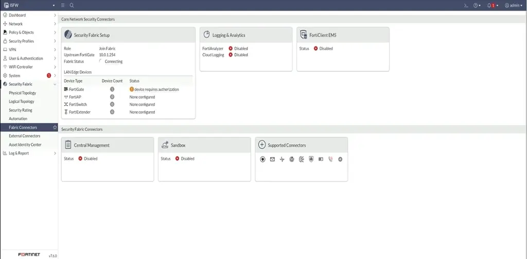
Authorize ISFW in the Security Fabric
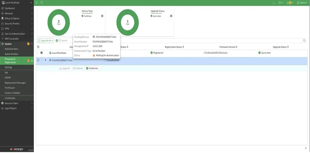
System > Formware Regestration > FGVM01000000077464> Authorize > After Refresh Webpage
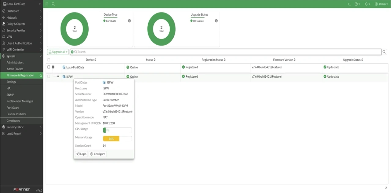
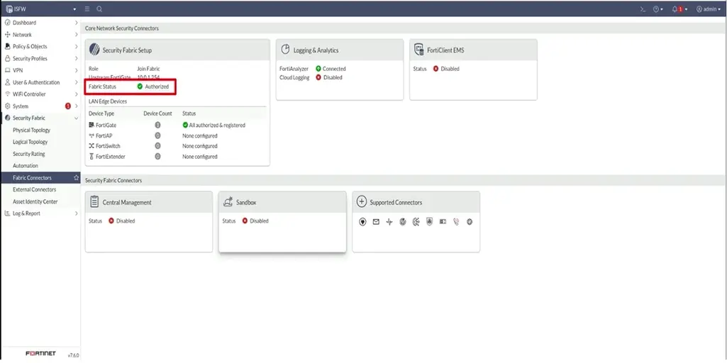
Explore the Security Fabric
Security Fabric > Physical Topology > Update Now
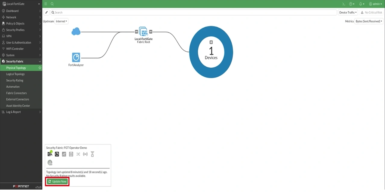
Security Fabric > Logical Topology
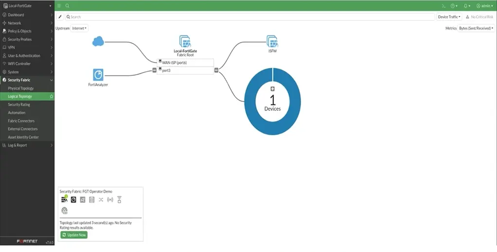
Policy & Objects > Addresses > Create New
Name: MyDemoSubnet IP/Network: 192.168.100.0/24 Fabric global-object [v]
OK>
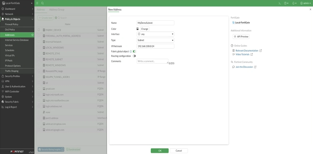
Now MyDemoSubnet on 2 devices
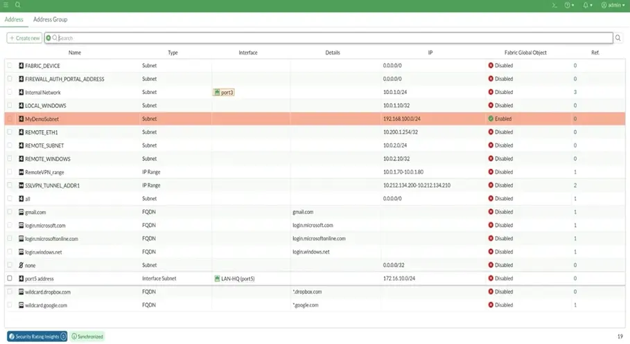
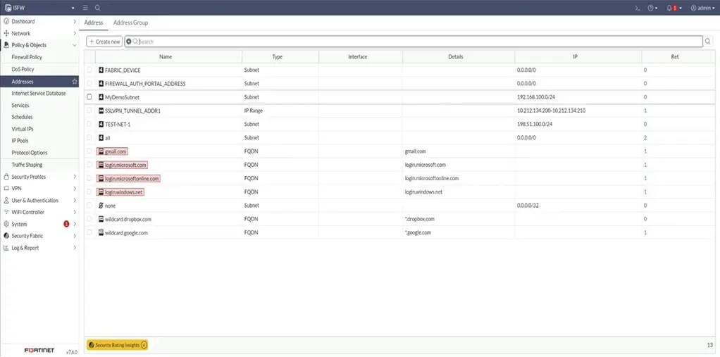
Examine current Security Fabric rating and apply recomendations
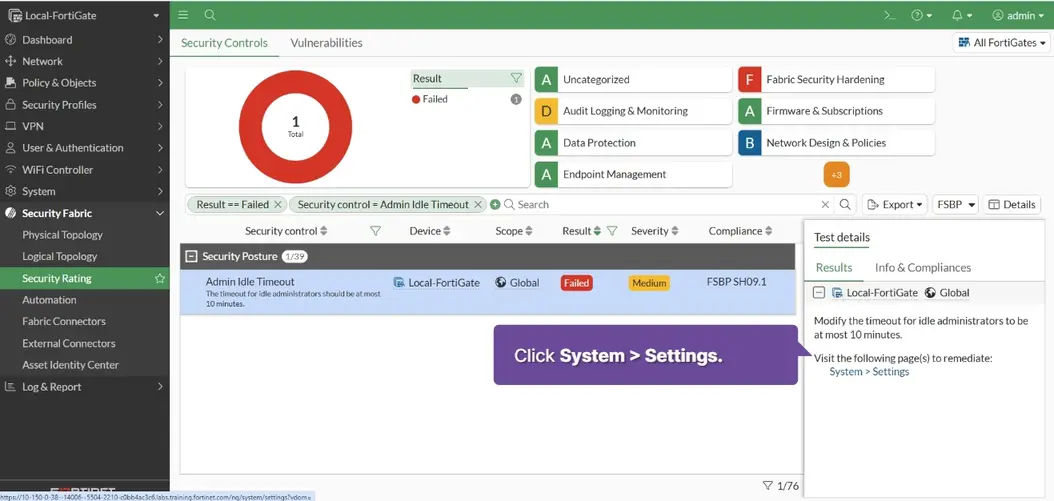
Security Fabric > Security Rating >
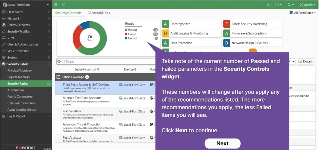
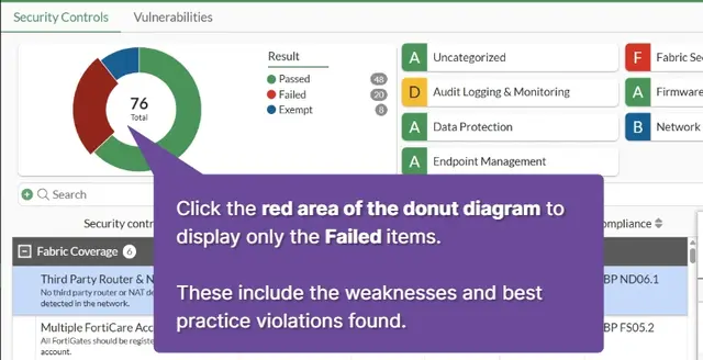
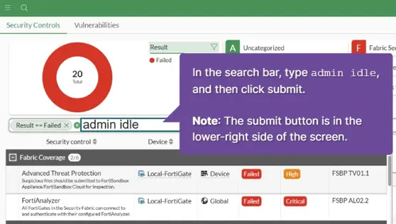
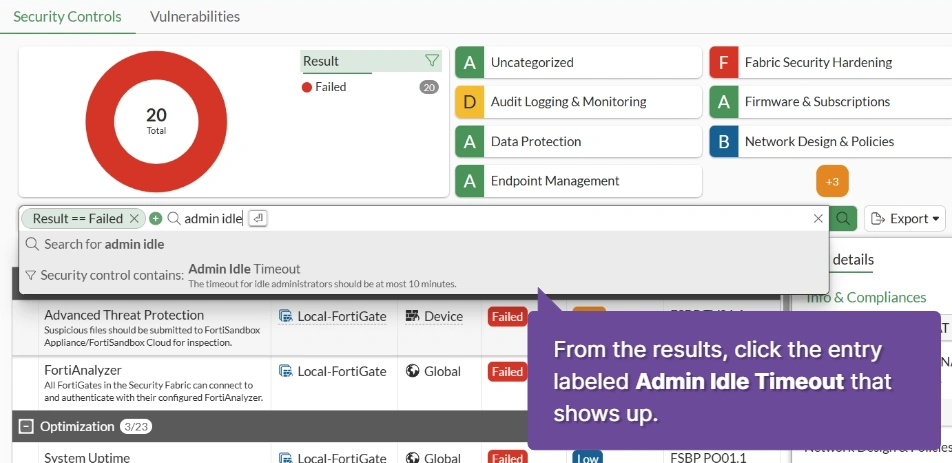
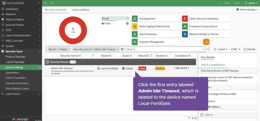
Admin Idle Timeout The timeout for idle administrator sessions is currently set to 10 minutes. This is one of the parameters that does not meet industry best practices, which is why it is marked as Failed. As indicated in the GUI, this parameter should be set to 10 minutes or less.
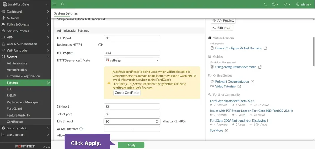
System > Settings
Scroll down the System Settings page to find the ldle timeout type 10 > Apple
Click [x] remove the two filters
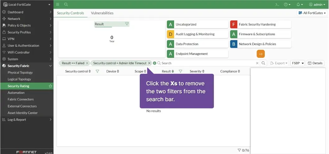
Note that the current number of Passed and Failed parameters was updated by increasing and reducing each one respectively by 1. You can repeat the same process to fix other parameters, making your device more secure.
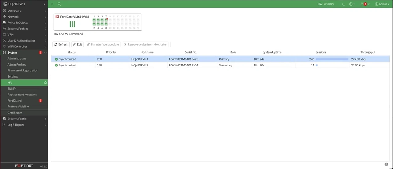
Fortigate Hight Availability (HA)
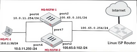
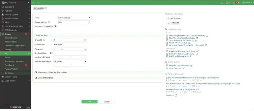
Configure HA on the primary unit
System > HA > Mode: Active-Passive
Device priority 200, Group ID 5, Group Name HA-DEMO, Password password, Session pickup [x], Heartbeat inteface port7, > OK
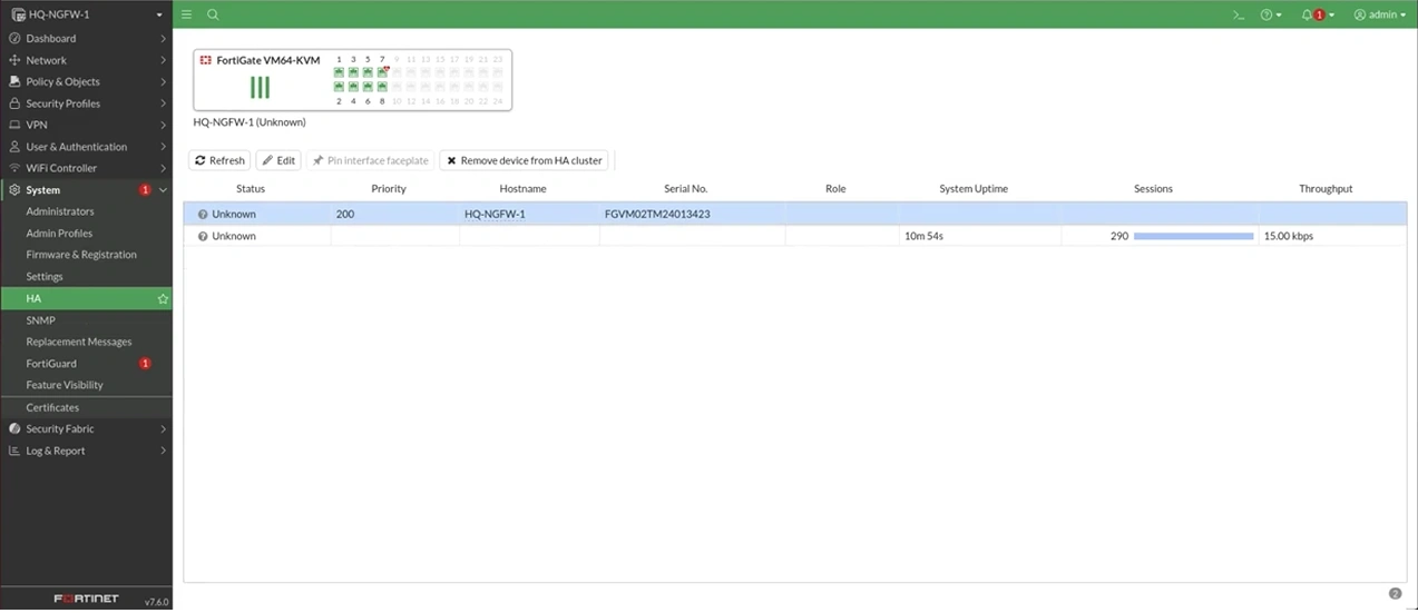
Refresh webpage
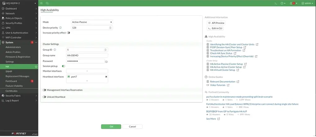
Configure HA on the secondary unit
System > HA > Mode: Active-Passive
Device priority 128, Group ID 5, Group Name HA-DEMO, Password password, Session pickup [x], Heartbeat inteface port7, > OK
Refresh webpage
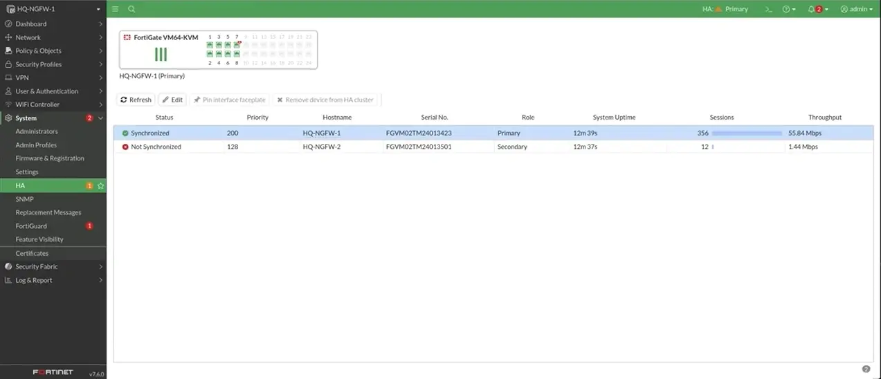
Verify the HA cluster
Refresh webpage > Status can be Synchronized
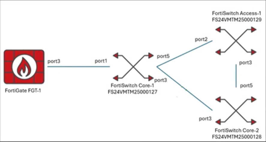
FortiLink
Verify the initial configuration of the three FortiSwitch devices
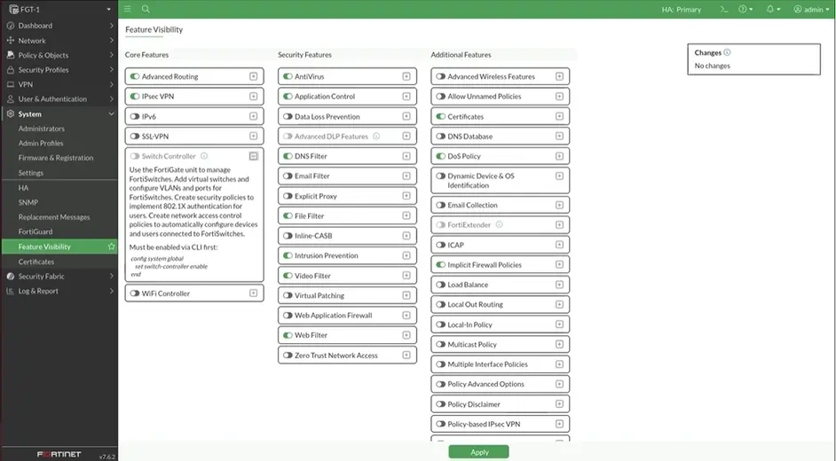
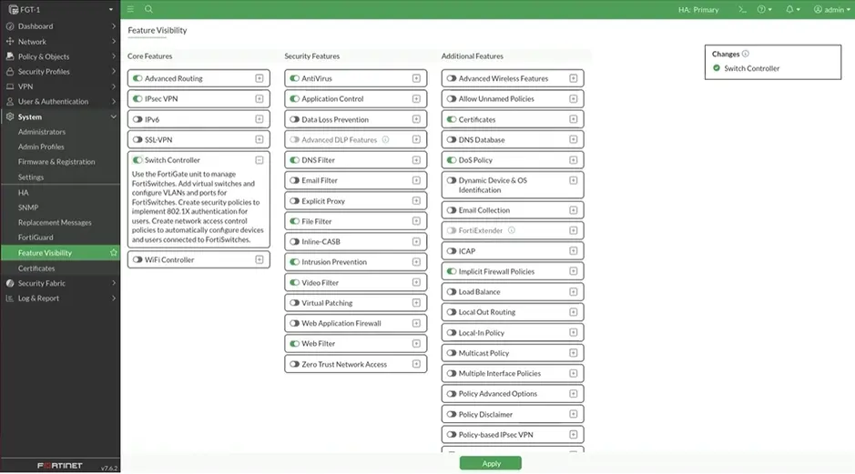
System > Feature Visibility > Switch Controller
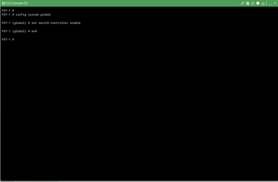
Open CLI Console
System > Feature Visibility > Switch Controller on [x] > Apply
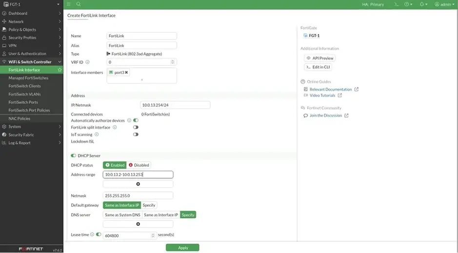
Wifi & Switch Controller > FortiLink Interface > Create FortiLink Inerface
Name: Fortilink Alies FortiLink, Inteface members port3, IP/Netmask 10.0.13.254/24 Automatically authorize devices [x]
Address range 10.0.13.2-10.0.13.253
Verify and test the management of the FortiSwitch devices form FortiGate
Refresh webpage
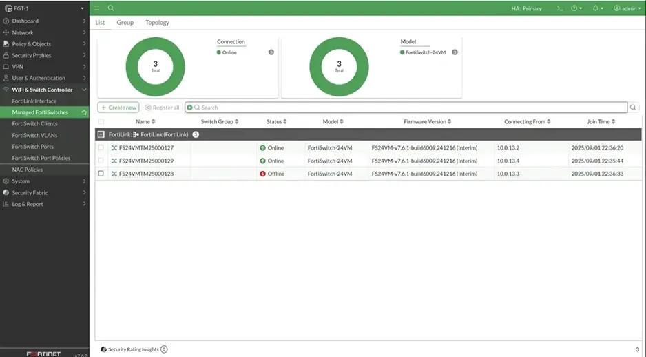
Wifi & Switch Controller > Managed FortiSwitches >
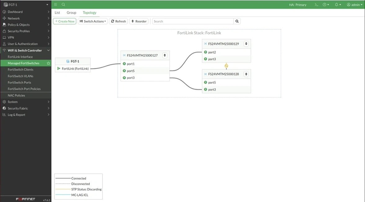
Rename switches
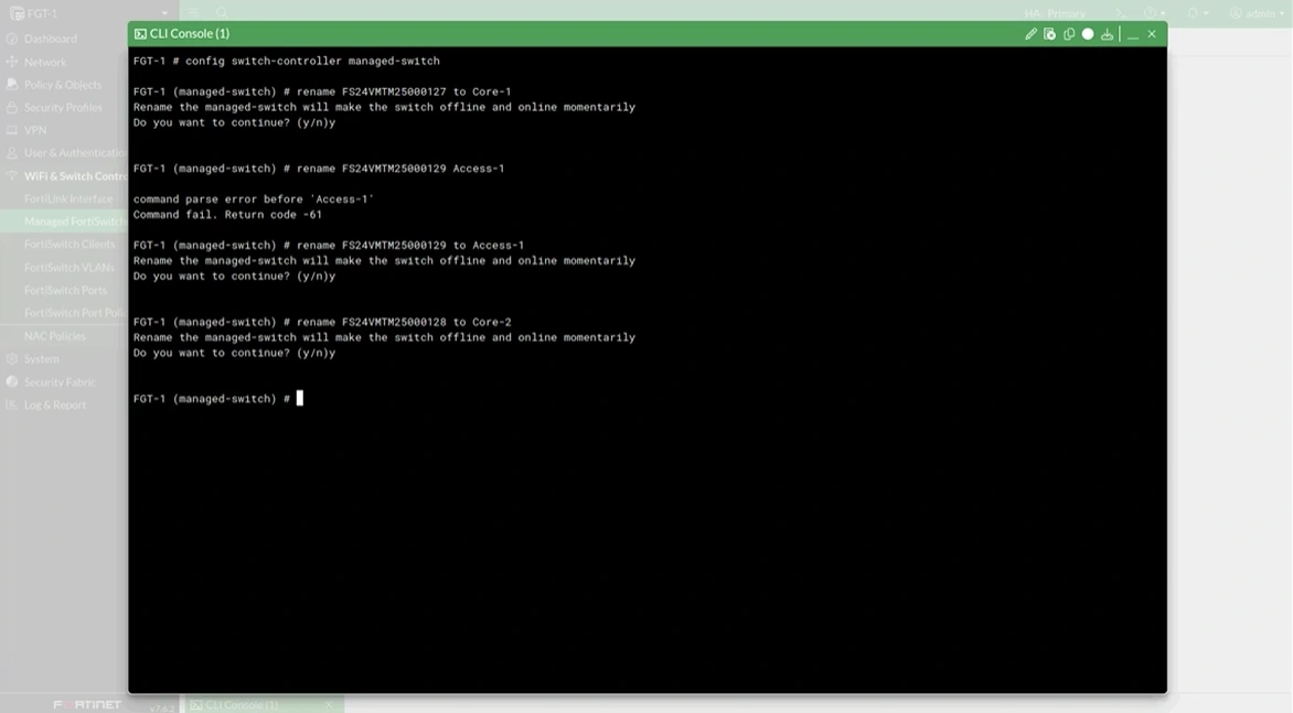
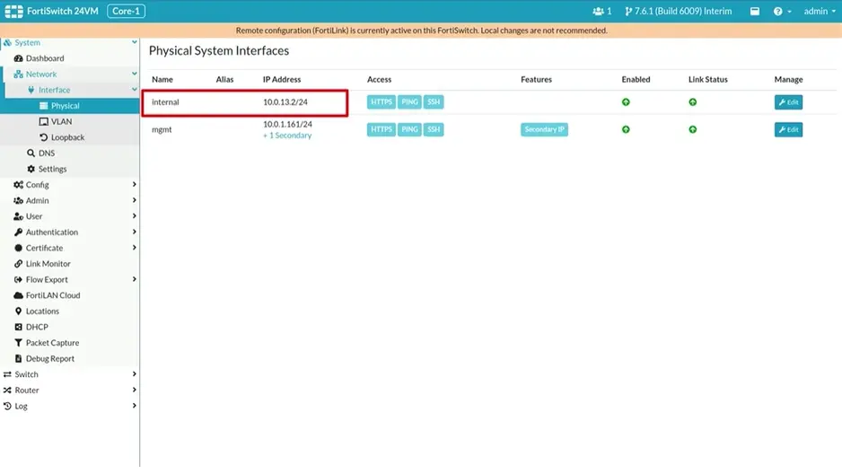
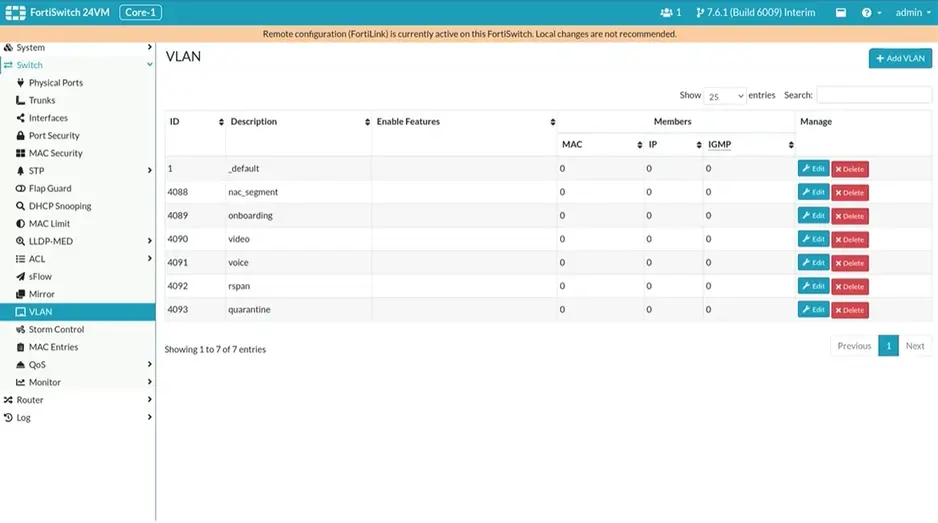
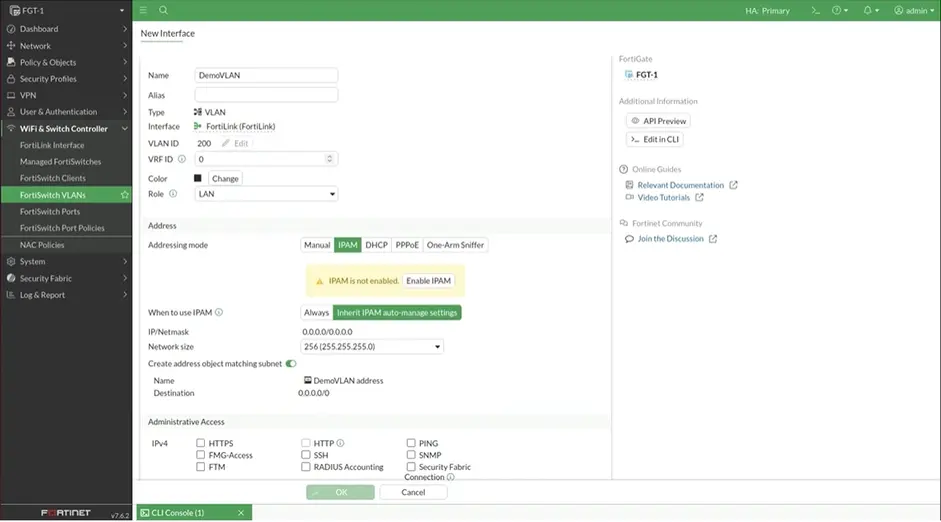
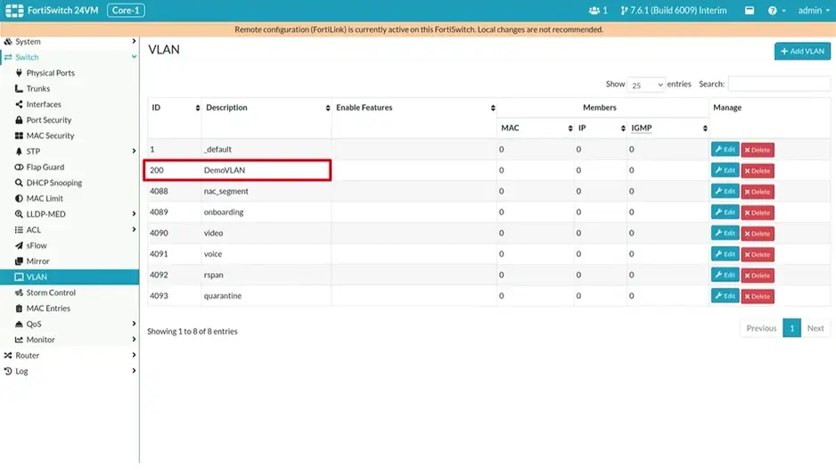
Wifi & Switch Controller > FortiSwitch VLANs > + Create >
Name: DEMOVLAN VLAN ID 200 > OK